Please see image below. I want to use a few proximity sensor switches for a lift /elevator project for my old/heavy German shepherd dog using an arduino UNO. Travel 6 Ft.
2 questions please if you will.
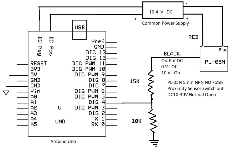
Will this switch connection work?
What value resistor do I need.
The 10.4 Volts DC will be coming from 8 X AA rechargeable batteries.
The lift will raise and lower 440 lbs the 6 ft in 10 seconds.
The switches are:
PL-05N 5mm NPN NO Fotek Proximity Sensor Switch out DC10-30V Normal Open
from ebay. I plan to use them for top and bottom limits and open/close on 2 doors.
Sensor seems to be a 3-wire NPN type (internal switch to ground) with a weak pull up (47k) to it's supply.
If so, you can connect the output directly to a digital input pin.
Or use a 10k resistor (as in your drawing) if you're not sure.
Should work both ways.
Leo..
Edit:
A 10k:15k divider with the sensor's internal 47k pull up won't give a proper HIGH (1.75volt).
Another solution is internal pull up on the input pin, and a diode (1N4148) between pin and sensor.
Cathode to sensor.
Just to be sure... This is now what I'm planning using the recommended divider.
I took my electricity courses 45 years and am obviously more than rusty:)