Here's a picture of the external power supply and it's separate power cable:
I tried the sketches there and they didn't work either
This is what I got in the serial monitor, I have no idea what it means:
RF24/examples/scanner/
SPI Speedz = 10 Mhz
STATUS = 0xff R
RF24/examples/scanner/
SPI Speedz = 10 Mhz
STATUS = 0xff R
RF24/examples/scanner/
SPI Speedz = 10 Mhz
STATUS = 0xff R
RF24/exaDS=1 TX_DF=1 RX_PIPE=7 TX_FULL=1
RX_ADDR_P0-1 = 0x7f00000000 0xffff7f0000
RX_ADDR_P2-5 = 0x7f 0xff 0x7f 0x00
TX_ADDR = 0xffffffff7f
RX_PW_P0-6 = 0x00 0x7f 0xff 0x00 0x00 0x00
EN_AA = 0x7f
EN_RXADDR = 0x7f
RF_CH = 0x00
RF_SETUP = 0x00
CONFIG = 0x00
DYNPD/FEATURE = 0x7f 0x00
Data Rate = 1 MBPS
Model = nRF24L01+
CRC Length = 8 bits
PA Power = PA_MIN
ARC = 0
000000000000000011111111111111112222222222222222333333333333333344444444444444445555555555555555666666666666666677777777777777
0123456789ABCDEF0123456789ABCDEF0123456789ABCDEF0123456789ABCDEF0123456789ABCDEF0123456789ABCDEF0123456789ABCDEF0123456789ABCD
D
RF24/examples/scanner/
SPI Speedz = 10 Mhz
STATUS = 0xff RX_DR=1 TX_DS=1 TX_DF=1 RX_PIPE=7 TX_FULL=1
RX_ADDR_P0-1 = 0xffffffff7f 0xffffffffff
RX_ADDR_P2-5 = 0x7f 0xff 0x7f 0xff
TX_ADDR = 0xffffffff03
RX_PW_P0-6 = 0xff 0x7f 0xff 0x00 0x00 0x00
EN_AA = 0xff
EN_RXADDR = 0x7f
RF_CH = 0x00
RF_SETUP = 0x00
CONFIG = 0x00
DYNPD/FEATURE = 0x7f 0x00
Data Rate = 1 MBPS
Model = nRF24L01+
CRC Length = 16 bits
PA Power = PA_MIN
ARC = 0
000000000000000011111111111111112222222222222222333333333333333344444444444444445555555555555555666666666666666677777777777777
0123456789ABCDEF0123456789ABCDEF0123456789ABCDEF0123456789ABCDEF0123456789ABCDEF0123456789ABCDEF0123456789ABCDEF0123456789ABCD
----------------------------------------------------------------------------------------------------1111111111111111--1111-111
444444444444444444444444443343444434333434433334334333334333333433333333443333443444444544444444444444444444444444444444444454
FFFFFFFFFFFFFFFFFFFFFFFFFFFFFFFFFFFFFFFFFFFFFFFFFFFFFFFFFFFFFFFFFFFFFFFFFFFFFFFFFFFFFFFFFFFFFFFFFFFFFFFFFFFFFFFFFFFFFFFFFFFFFF
FFFFFFFFFFFFFFFFFFFFFFFFFFFFFFFFFFFFFFFFFFFFFFFFFFFFFFFFFFFFFFFFFFFFFFFFFFFFFFFFFFFFFFFFFFFFFFFFFFFFFFFFFFFFFFFFFFFFFFFFFFFFFF
--------------------------------------------------------------1111111111111111111111111111111111111111111111111111111111------
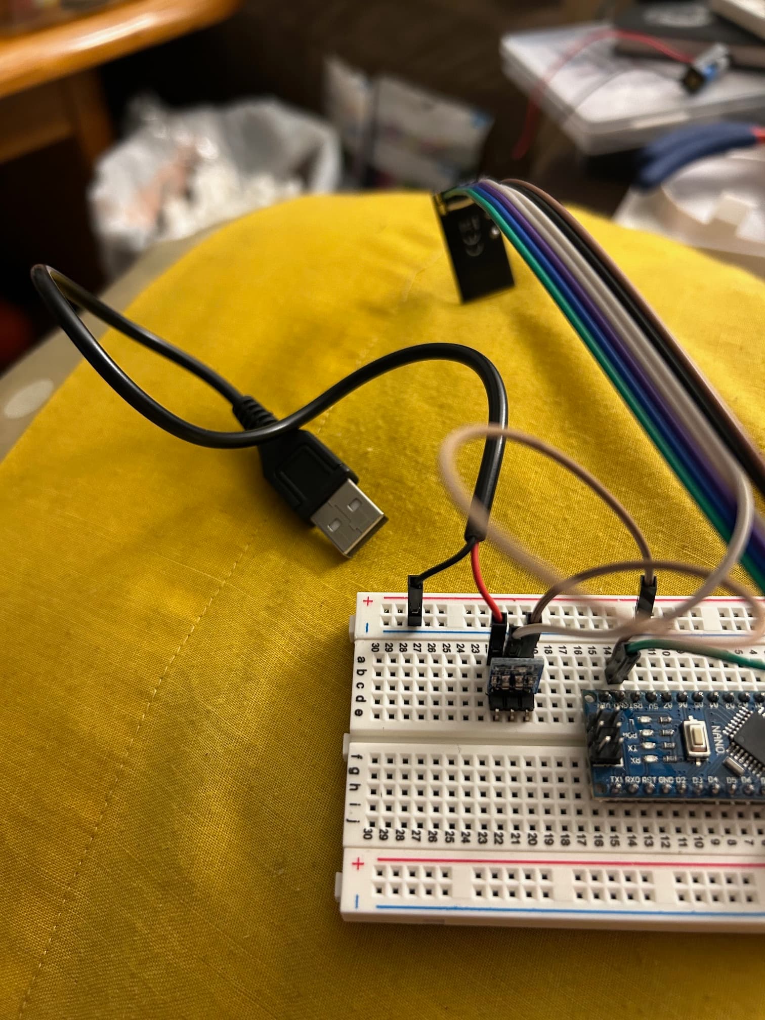
Considering both nRFs are communicating with the Nanos and I'm using external 3.3V power supplies with capacitors from 3.3V to ground (and the external power supply ground is tied to the Nano ground) what else could be causing the nRFs to not communicate with each other?
What is the part number of the 3v3 regulators you have on those breadboards ? Normally, the data sheets of such regulators specify capacitors on both the supply side and the output side. I see only one capacitor.
Here is an NRF24L01 adapter and schematic. It has 4 capacitors for the regulator.
I swapped out the 3.3v regulators I was using with AMS1117-3.3V. I verified it has capacitors on both the supply and output side
If this gibberish is on both boards and it's almost identical, then the receiving modules are working properly.
So I take it there’s nothing else to try
Its clear you have a problem hardware wise, and are also using an outdated version of the RF24 library.
I would suggest first updating to the current library version v1.5.0
Then follow the official guide at RF24/COMMON_ISSUES.md at master · nRF24/RF24 · GitHub using the official gettingStarted example included with the library.
It will pretty much tell you where the problems are, it is actually fairly simple to troubleshoot.
It sounds to me like you have a power supply problem, and/or a wiring issue somewhere, whether that be a bad wire or something, I don’t know. I would say bad radios at this point, but it sounds like you’ve used various radios.
You also need to be very clear on what exactly is happening if you get stuck.
It looks like you have used this tutorial: Simple nRF24L01+ 2.4GHz transceiver demo
He has recommended an ancient version of the NRF24L01 library but, for that simple sketch, you should use the latest version (as suggested by @TMRh20 as I was composing this.)
You could also set the power on the devices to low with radio.setPALevel(RF24_PA_MIN) to make it less sensitive to power supply issues.
This also looks odd but it may simply be from one of the other sketches you've been asked to try:
Usually it is 16.
EDIT
I've looked again and I can't see anything which explicitly sets the CRC length to 8 in the sketch in post #2. This then indicates either (a) a power supply issue, bad common ground etc. or (b) that the module, possibly because of the cable length, is unable to support the 10MHz bus speed.
The connection diagram in the "Robin2" tutorial (where you appear to have got your initial code) is misleading in that it shows the use of an external supply but fails to show that all the grounds should be connected together. Some NRF24L01 modules have resistors in the SPI lines which limit the maximum bus speed, as can long cables, and can cause erratic performance. The trouble shooting guide linked in post #30 shows how to configure a lower SPI bus speed.
1 Like