nRF24L01+ not working

I'm trying to connect an arduino uno (as receiver) with a raspberry pi (transmitter) using two nRF24L01+ modules. However, I can't seem to get them to work.

if (radio.available(&pipe)) {
    char text[32] = {0};
    radio.read(&text, sizeof(text));
    Serial.print("Received: ");
    Serial.println(text);
    Serial.println(pipe);
  }

This is the code I used in the main loop, and for some reason, radio.available always seems to be true even if the other transmitter is turned off? The pipe keeps printing 0 and its not receiving anything.
EDIT: this issue was caused by broken pin, but still not receiving anything

Here is the setup for the radio:

  RF24 radio(9, 10);  // ce, csn
  const byte address[5] = {0xe7, 0xe7, 0xe7, 0xe7, 0xe7};  // same as the pi's writing pipe

  radio.begin();
  radio.openReadingPipe(0, address);
  radio.setPALevel(RF24_PA_LOW);
  radio.enableAckPayload();
  radio.setAutoAck(true);
  radio.setDataRate(RF24_1MBPS);
  radio.setChannel(0x76); // also the same channel
  radio.startListening();

Here is the raspberry pi code (sorry couldn't copy it here):

My connections from nrf24 -> uno:
gnd -> gnd
vcc -> 3.3v
ce -> 9
csn -> 10
sck -> 13
mosi -> 11
miso -> 12

Post complete sketch in "code blocks."

It's on my raspberry pi and I can't really copy it unto the computer im using right now.

Yes, you can. You do not want to. Big difference.

from lib_nrf24 import NRF24
import spidev
import RPi.GPIO as GPIO
import keyboard
import time
import sys
import tty
import termios
import pigpio

pi = pigpio.pi()
ce_pin = 25

GPIO.setmode(GPIO.BCM)
GPIO.setup(22, GPIO.OUT)
GPIO.setup(23, GPIO.OUT)

pipes = [[0xe7, 0xe7, 0xe7, 0xe7, 0xe7]]

radio = NRF24(GPIO, spidev.SpiDev())
radio.begin(0, 17)
radio.setPayloadSize(32)
radio.setChannel(0x76)
radio.setDataRate(NRF24.BR_1MBPS)
radio.setPALevel(NRF24.PA_MIN)
radio.setAutoAck(True)
radio.enableDynamicPayloads()
radio.enableAckPayload()
radio.openWritingPipe(pipes[0])
radio.stopListening()

pitch = 0
roll = 0
yaw = 0

def send_message(text: str):
    if len(text) > 32:
        text = text[:32]
    message = list(text)
    radio.write(message)

    if radio.isAckPayloadAvailable():
        returnedPL = []
        radio.read(returnedPL, radio.getDynamicPayloadSize())
        print("Returned payload was {}".format(returnedPL))
    else:
        print("No payload received")

while True:
    send_message("Hello World")
    time.sleep(0.1)

Posting an annotated schematic will help you get an accurate answer in a relative short time. Be sure it shows power sources, power and ground connections and links to extra hardware. Also a photo of your test setup would be helpful.

My connections from nrf24 -> uno:
gnd -> gnd
vcc -> 3.3v
ce -> 9
csn -> 10
sck -> 13
mosi -> 11
miso -> 12

How was the broken pin involved, how was the pin fixed, and how do you determine the issue is not caused by the previously broken pin? Tie the information together.

Power supply issues. These are common issues addressed at

It looks like you are using the PA+LNA modules, which require a good power supply. An official Uno board might be able to handle one, but the Raspberry Pi will require something to convert 5v down to 3.3v for the radios like the following adapter.

I think I know what your problem is but I would like to see a schematic to be sure.
Power Stability Issues with RF24 Radio Modules

As described in the RF24 Common Issues Guide, radio modules, especially the PA+LNA versions, are highly reliant on a stable power source. See @TMRh20 posting. The 3.3V output from Arduino is not stable enough for these modules in many applications. While they may work with an inadequate power supply, you may experience lost packets or reduced reception compared to modules powered by a more stable source.

Symptoms of Power Issues:

  • Radio module performance may improve when touched, indicating power stability issues.
  • These issues are often caused by the absence of a capacitor, a common cost-saving omission by some manufacturers.

Temporary Patch :

  • Add Capacitors: Place capacitors close to the VCC and GND pins of the radio module. A 10uF capacitor is usually sufficient, but the exact value can depend on your circuit layout.
  • Use Low ESR Capacitors: Capacitors with low Equivalent Series Resistance (ESR) are recommended, as they provide better power stability and performance.
  • Be sure the transmitter and receiver are at least a meter apart, more is better.

Adding the appropriate capacitors can greatly improve the reliability of your RF24 module by ensuring a stable power supply, thus minimizing packet loss and enhancing overall performance. A separate power supply for the radios is the best solution.

After some testing I found out that my raspberry pi does seem to have undervoltage problems. I will try to find an adapter and add the capacitors.

Other than these issues, when I run radio.printDetails() on my raspberry pi the channel isnt what I set and seems to alter randomly whenever i rerun the script. Also the address isn't the one I set. In my code i put it at radio.openWritingPipe([0xe7, 0xe7, 0xe7, 0xe7, 0xe7]) but the address seems to be 0xfdfdfdfdfd?

That means the radio and the RPI are not 'talking' correctly over SPI.

This is usually due to incorrect wiring, but could be related to power supply issues. See the common issues link I posted above.

So I got myself an adapter for the module but the problems are still persisting.

Well, you need to first sort out any wiring issues & make sure your pins are correct.

Where are you at in troubleshooting? Have you gotten correct 'printDetails();' output yet?

Have you tested with the base RF24 gettingstarted examples?

We need more info on what is going wrong...

1 Like

I will assume you are powering it with the Arduino. If so that can be very problematic.

Gil's Crispy Critter Rules for Processor Hardware:

  1. Rule #1: An Arduino is NOT a Power Supply!
  2. Rule #2: Never connect anything inductive (motors, speakers) directly to an Arduino!
  3. Rule #3: Avoid connecting or disconnecting wires while the power is on.
  4. Rule #4: Do not apply power to any pin unless you are certain of what you're doing.
  5. Rule #5: Do not exceed the maximum voltage ratings.
  6. Rule #6: Many Arduinos cannot power transmitters directly.
  7. Rule #7: Before powering your project, take a break and double-check the wiring.

LaryD’s Corollaries:

  1. Coro #1: When starting out, add a 220Ξ© resistor in series with both input and output pins to protect against shorts.
  2. Coro #2: Invest in a Digital Multi-Meter (DMM) to measure voltages, currents, and resistance.

Note: Violating these rules can turn your Arduinos into crispy critters. For optimal performance, keep your wires under 25 cm (10 inches).

Additional Tips:

  • The L293 motor driver, though common, is inefficient as it can lose around 3V as heat when driving both legs of a motor. Consider using a motor driver with MOSFET outputs to reduce heat loss and conserve battery power.
  • The nRF24 radios do not work very well when powered with an Arduino even if the 5V adapter is used.
  • For more on powering Arduino boards, explore this guide: Powering Alternatives for Arduino Boards.

I have rechecked my wiring multiple time and they seem to be correct.
Pin 1 (3.3V or 5V) β†’ VCC on adapter
Pin 6 (GND) β†’ GND on adapter
Pin 11 (GPIO17) β†’ CE on adapter
Pin 24 (GPIO8 / CE0) β†’ CSN on adapter
Pin 23 (GPIO11 / SCLK) β†’ SCK on adapter
Pin 19 (GPIO10 / MOSI) β†’ MOSI on adapter
Pin 21 (GPIO9 / MISO) β†’ MISO on adapter

My problem is still that printDetails() doesn't show the correct output. The channel isn't what I set and the addresses, pa level, etc either. I then tried with the examples given by the library im using, and once again the printDetails arent correct. In the example, the address for the writing pipe is set to [0xe7, 0xe7, 0xe7, 0xe7, -0xe7] but in the printDetails the tx_addr = 0x7c7c7c7c7cfc . Also, the channel is set to 0x60 but the output of rf_ch = 0xce. I have used another spare radio module and the results were the same. I have also confirmed that the SPI is enabled and the files are there.

The adapter should be connected to a 5V pin, not 3.3v.

Secondly, the printDetails(); output would be correct if SPI was working properly. 99% of the time, this fails because of incorrect wiring or bad connections. Double check the library you are using to make sure it uses GPIO numbers not pin numbers for pin selection.

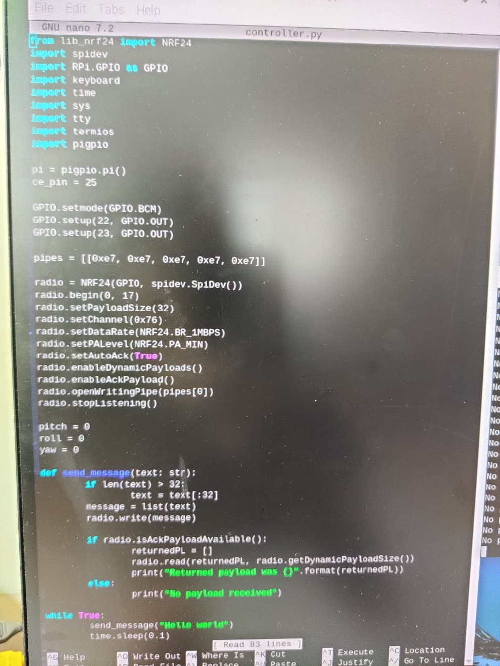
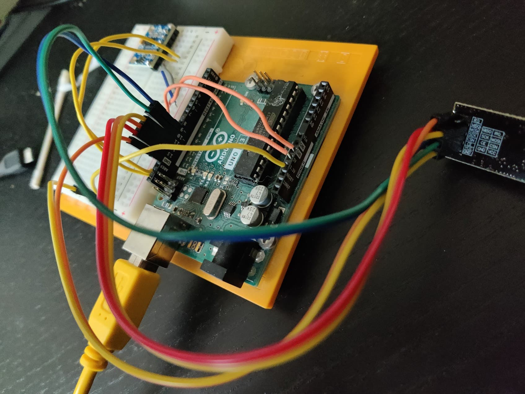
So i changed the pi I was using to a newer one (pi 5). Since it doesnt support the old gpio tools, i am now using a different module (circuitpython_nrf24l01). I have succeeded in getting the print_details() right, however i have not yet succeeded in achieving any communication between the 2 devices. I haven't changed anything on the arduino side (receiver), have adapters on both devices and made sure all the wiring is correct.

Updated pi code:

import gpiozero
import keyboard
import time
import sys
import tty
import termios

from digitalio import DigitalInOut
import spidev
from circuitpython_nrf24l01.rf24 import RF24
import board

print("running controller.py")

pipes = [[0xe7, 0xe7, 0xe7, 0xe7, 0xe7]]
SPI_BUS = spidev.SpiDev()
CSN_PIN = 0
CE_PIN = DigitalInOut(board.D22)

pitch = 0
roll = 0
yaw = 0

radio = RF24(SPI_BUS, CSN_PIN, CE_PIN)
radio.pa_level = -12
radio.channel = 76

radio.open_tx_pipe(pipes[0])
radio.dynamic_payloads = False
radio.payload_length = 32

radio.listen = False

radio.print_details(dump_pipes=True)

def send_message(radio, message: bytes) -> bool:
	if isinstance(message, str):
		message = message.encode("utf-8")
		
	print("step 1")
	
	if not radio.write(message):
		print("Message failed to send.")
		return None
		
	print("step 2")
	
	if radio.ack:
		payload = radio.read()
		print("ACK payload received:", payload)
		return payload
        
	print("Message sent, no ACK payload.")
	return None

while True:
	print("trying to send")
	send_message(radio, "Hello world")
	time.sleep(1)

Print details before the write() is called (on the pi):

Is a plus variant        True
Channel                  76 ~ 2.476 GHz
RF Data Rate             1 Mbps
RF Power Amplifier       -12 dBm
RF Low Noise Amplifier   Enabled
CRC bytes                2
Address length           5 bytes
TX Payload lengths       32 bytes
Auto retry delay         1500 microseconds
Auto retry attempts      15 maximum
Re-use TX FIFO           False
Packets lost on current channel     0
Retry attempts made for last transmission  0
IRQ on Data Ready        Enabled    Data Ready           False
IRQ on Data Fail         Enabled    Data Failed          False
IRQ on Data Sent         Enabled    Data Sent            False
TX FIFO full             False      TX FIFO empty        True
RX FIFO full             False      RX FIFO empty        True
Ask no ACK               Allowed    Custom ACK Payload   Disabled
Dynamic Payloads         Disabled   Auto Acknowledgment  Enabled
Primary Mode             TX         Power Mode           Standby-I
TX address               0xE7E7E7E7E7
Pipe 0 ( open ) bound:   0xE7E7E7E7E7
        expecting 32 byte static payloads
Pipe 1 (closed) bound:   0xC2C2C2C2C2
Pipe 2 (closed) bound:   0xC2C2C2C2C3
Pipe 3 (closed) bound:   0xC2C2C2C2C4
Pipe 4 (closed) bound:   0xC2C2C2C2C5
Pipe 5 (closed) bound:   0xC2C2C2C2C6

after the write() function is called (on the pi):

Is a plus variant        True
Channel                  76 ~ 2.476 GHz
RF Data Rate             1 Mbps
RF Power Amplifier       -12 dBm
RF Low Noise Amplifier   Enabled
CRC bytes                2
Address length           5 bytes
TX Payload lengths       32 bytes
Auto retry delay         1500 microseconds
Auto retry attempts      15 maximum
Re-use TX FIFO           False
Packets lost on current channel     0
Retry attempts made for last transmission  0
IRQ on Data Ready        Enabled    Data Ready           False
IRQ on Data Fail         Enabled    Data Failed          False
IRQ on Data Sent         Enabled    Data Sent            False
TX FIFO full             True       TX FIFO empty        False
RX FIFO full             False      RX FIFO empty        True
Ask no ACK               Allowed    Custom ACK Payload   Disabled
Dynamic Payloads         Disabled   Auto Acknowledgment  Enabled
Primary Mode             TX         Power Mode           Standby-II

and the arduino output is the same as before (not receiving anything):

RX_ADDR_P2-5	= 0xc3 0xc4 0xc5 0xc6
TX_ADDR		= 0xe7e7e7e7e7
RX_PW_P0-6	= 0x20 0x20 0x20 0x20 0x20 0x20
EN_AA		= 0x3f
EN_RXADDR	= 0x03
RF_CH		= 0x76
RF_SETUP	= 0x05
CONFIG		= 0x0f
DYNPD/FEATURE	= 0x03 0x06
Data Rate	= 1 MBPS
Model		= nRF24L01+
CRC Length	= 16 bits
PA Power	= PA_HIGH
ARC		= 0

My main problem right now is that i do not know where the problem is occuring and if the transmitter or receiver isn't working.

Find an Arduino. Use an example in the RF24 library. If it works, and it should, you can look at power, wiring and code. The process of elimination to rule-out good devices.