My two nRF24l01+ modules don't communicate with each other no matter how I set the PA or how far I put them together, I tried to set them 3 meters apart with PA at HIGH and 2 feet apart with PA at MIN.
I use Arduino Uno as the receiver and a Nano clone as the transmitter.
here's pics of the Arduino uno wiring as schematic(its not fully accurate as the 3v3 reg is in the adapter which has capacitors in it but the spi connections are same)

and the physical uno

And this is a schematic and irl pic of the nano


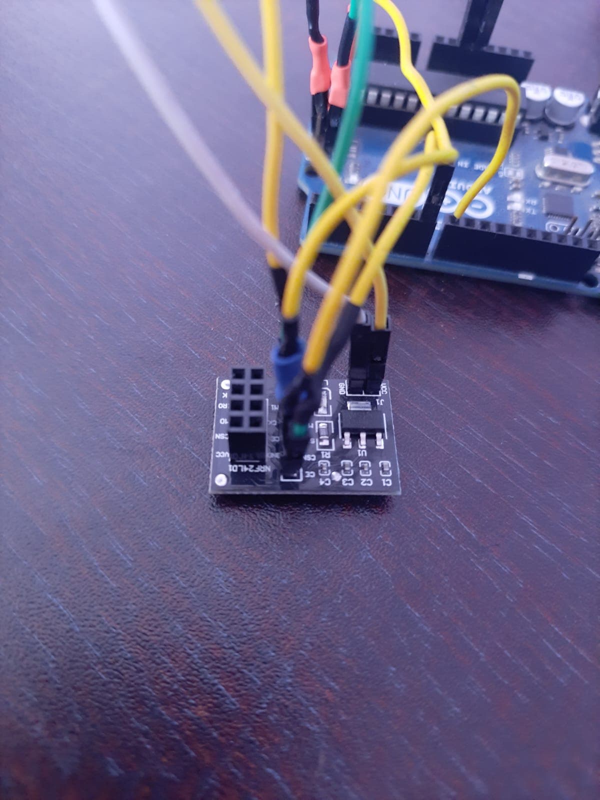
This is the adapter I am using
This is the output on the serial monitor after using Robin2's connection test code
CheckConnection Starting

FIRST WITH THE DEFAULT ADDRESSES after power on
  Note that RF24 does NOT reset when Arduino resets - only when power is removed
  If the numbers are mostly 0x00 or 0xff it means that the Arduino is not
     communicating with the nRF24

SPI Speedz	= 10 Mhz
STATUS		= 0x0e RX_DR=0 TX_DS=0 MAX_RT=0 RX_P_NO=7 TX_FULL=0
RX_ADDR_P0-1	= 0xe7e7e7e7e7 0xc2c2c2c2c2
RX_ADDR_P2-5	= 0xc3 0xc4 0xc5 0xc6
TX_ADDR		= 0xe7e7e7e7e7
RX_PW_P0-6	= 0x20 0x20 0x20 0x20 0x20 0x20
EN_AA		= 0x3f
EN_RXADDR	= 0x03
RF_CH		= 0x4c
RF_SETUP	= 0x07
CONFIG		= 0x0e
DYNPD/FEATURE	= 0x00 0x00
Data Rate	= 1 MBPS
Model		= nRF24L01+
CRC Length	= 16 bits
PA Power	= PA_MAX
ARC		= 0


AND NOW WITH ADDRESS AAAxR  0x41 41 41 78 52   ON P1
 and 250KBPS data rate


SPI Speedz	= 10 Mhz
STATUS		= 0x0e RX_DR=0 TX_DS=0 MAX_RT=0 RX_P_NO=7 TX_FULL=0
RX_ADDR_P0-1	= 0xe7e7e7e7e7 0x4141417852
RX_ADDR_P2-5	= 0xc3 0xc4 0xc5 0xc6
TX_ADDR		= 0xe7e7e7e7e7
RX_PW_P0-6	= 0x20 0x20 0x20 0x20 0x20 0x20
EN_AA		= 0x3f
EN_RXADDR	= 0x03
RF_CH		= 0x4c
RF_SETUP	= 0x27
CONFIG		= 0x0e
DYNPD/FEATURE	= 0x00 0x00
Data Rate	= 250 KBPS
Model		= nRF24L01+
CRC Length	= 16 bits
PA Power	= PA_MAX
ARC		= 0
I used the radio.isChipConnected() function is it outputted true for that so i don't know why the radios wont work.
Below is code for the transmitter
#include <SPI.h>
#include <nRF24L01.h>
#include <RF24.h>

#include <printf.h>

#define CE_PIN   7
#define CSN_PIN 8

const byte Address[] = { 0xCC, 0xCE, 0xCC, 0xCE, 0xCC};

RF24 radio(CE_PIN, CSN_PIN);

void setup() {
  // put your setup code here, to run once:
  Serial.begin(9600);
  Serial.println("  Tx Code Starting");

  radio.begin();
  radio.setDataRate( RF24_1MBPS );
  radio.setPALevel(RF24_PA_HIGH);
  radio.stopListening();
  radio.openWritingPipe(Address);
}

void loop() {
  // put your main code here, to run repeatedly:
 const char text[] = "Hello";
  bool rslt = radio.write(&text, sizeof(text));

 if (rslt)
  Serial.println("Tx Success Ack Received");

 else
  Serial.println("Tx Failed");

 delay(70);
}
Below is code for the receiver
#include <SPI.h>
#include <nRF24L01.h>
#include <RF24.h>

#include <printf.h>

#define CE_PIN   7
#define CSN_PIN 8

const byte Address[] = { 0xCC, 0xCE, 0xCC, 0xCE, 0xCC};

RF24 radio(CE_PIN, CSN_PIN);

char data[] = "";
bool newData = false;

void setup() {
  // put your setup code here, to run once:
   Serial.begin(9600);
  Serial.println("  Rx Code Starting");

  radio.begin();
  radio.setDataRate( RF24_1MBPS );
  radio.setPALevel(RF24_PA_HIGH);
  radio.openReadingPipe(1, Address);
  radio.startListening();
}

void loop() {
  // put your main code here, to run repeatedly:
  if ( radio.available() ) {
   radio.read(&data, sizeof(data));
   newData = true;
  }

 if (newData == true){
  Serial.print("Message received:");
  Serial.println(data);
  newData = false;
 }

}