Hello all, I am new to op amps and could use some guidance. I would appreciate any help you guys can provide!
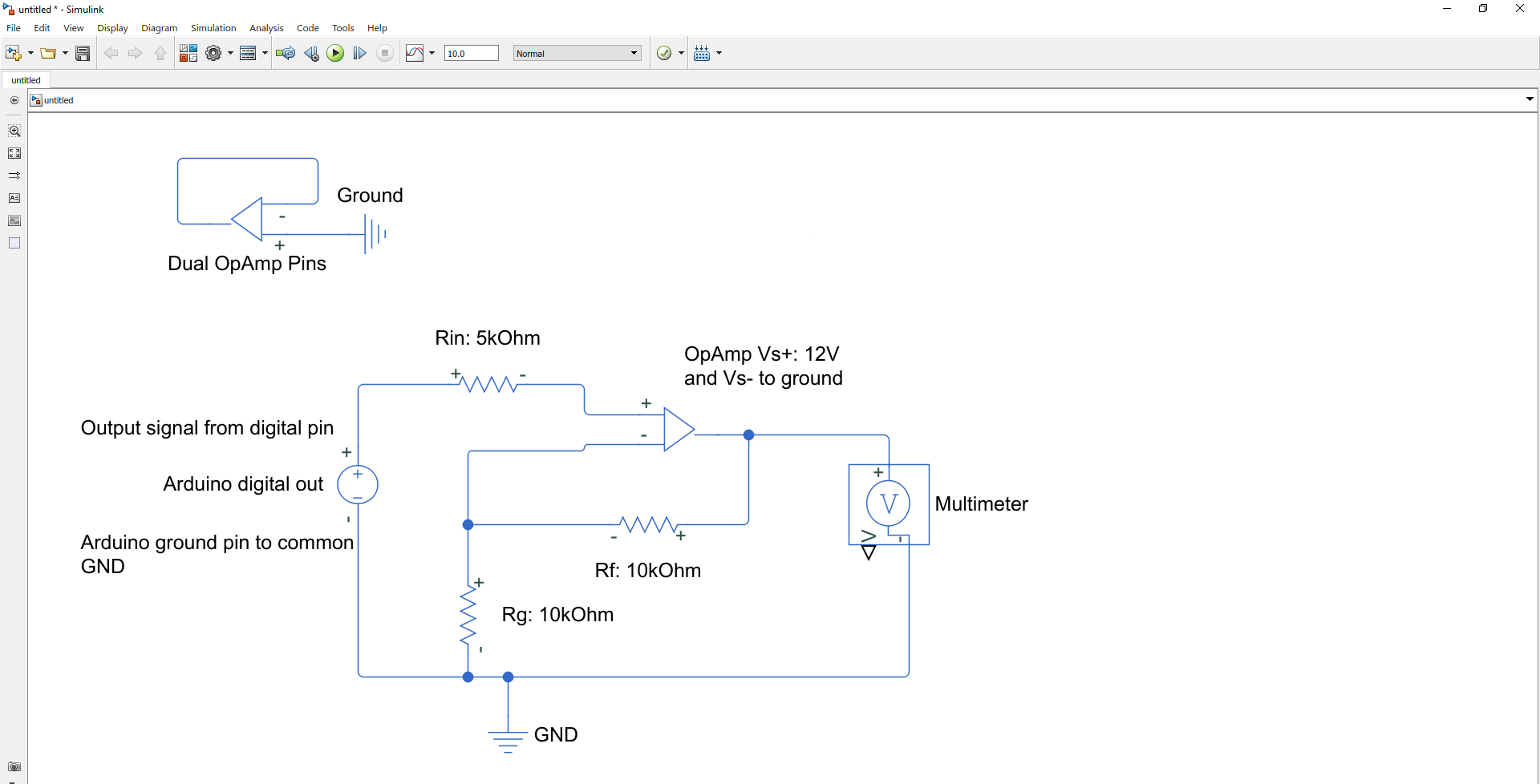
Intent: Amplify analogWrite signal (5V PWM) to 0 - 10 V analog signal. This signal will be input to a motor controller.
Problem: I am currently seeing an inverted output from 10.5V - 9.7V.
Question: How do I get to the desired output? Is this a wiring issue or using the wrong components?
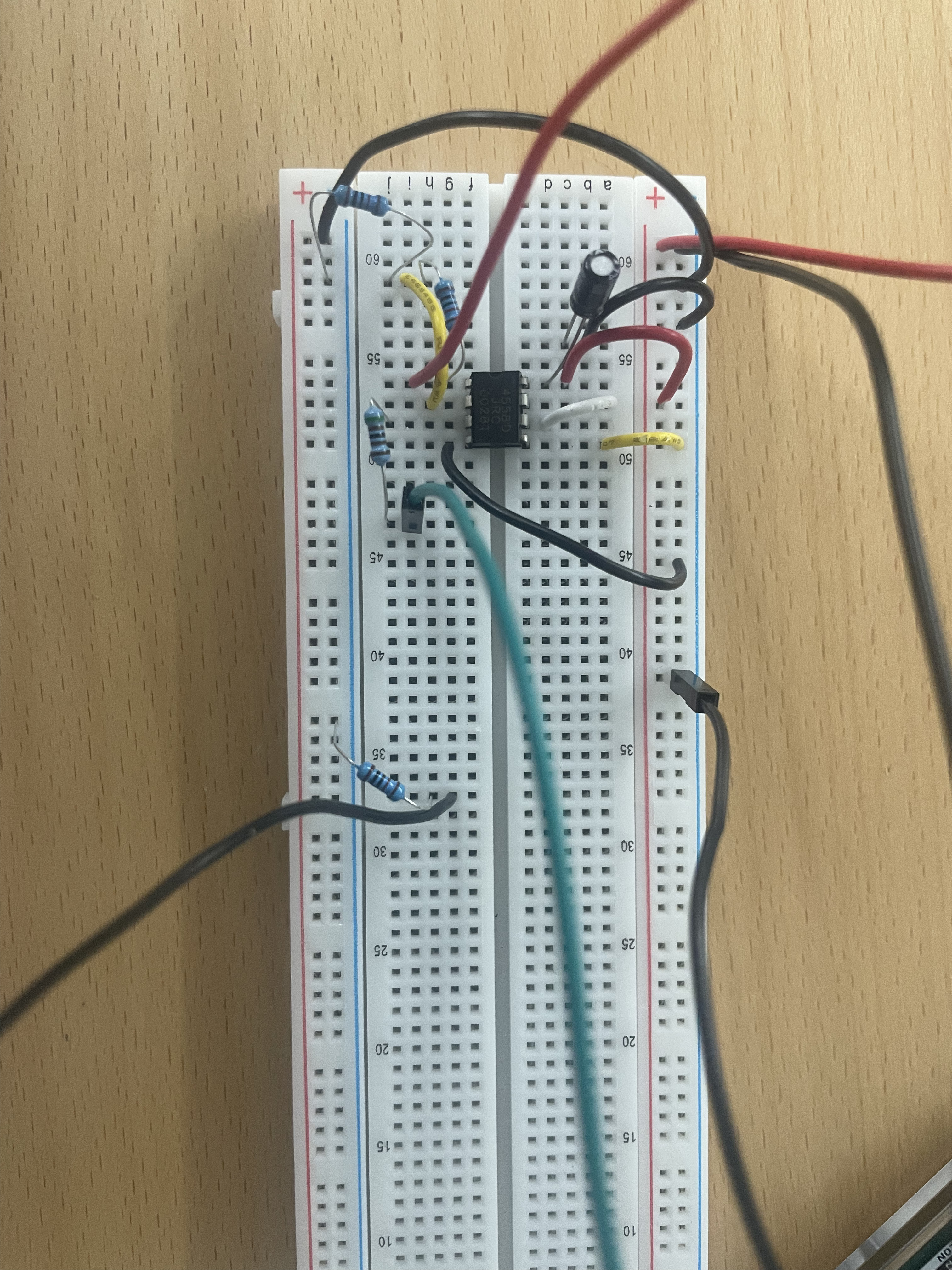
I have the op-amp wired as a non-inverting amplifier circuit per Figure 18 in this data sheet: . I also wired IN2- to output and IN2+ to ground to terminate open pins.
I am measuring the output using a multimeter with a 10kOhm resistor between the multimeter negative terminal and ground to simulate load resistance.
Supply(+) = 12 VDC
Supply(-) -> GND
IN+ = 5V PWM (I also tried 0V - 5V digital signal)
IN- -> GND
Rf = 10 kOhm
Rg = 10 kOhm
Rin = 5.1 kOhm
Code sends PWM signal to digital pin based on desired flow rate from Serial input via PC (the motor is driving a fan).
Arduino Code:
int MotPin1 = 2;

void setup() {
  // put your setup code here, to run once:
  Serial.begin(9600);
  Serial.println("<Arduino is ready>");
  pinMode(MotPin1, OUTPUT);
}


void loop() {
  // put your main code here, to run repeatedly:

  Serial.println("Please enter desired flow rate (0.7 - 3.9)");

  while(Serial.available() == 0){
    // Do nothing
  }

  float flow = Serial.parseFloat(); // parse flot flow rate in range: 0.7 - 3.9
  motor_speed(MotPin1, flow); // set motor speed necessary pwm signal given flow rate. input is a float value while output is integer

  // Cycle serial read until nothing is available
  while(Serial.available()  > 0){
    Serial.read();
  }

  delay(2000);  // wait 2 seconds for motor to adjust
}

// Convert desired flow rate to arduino PWM
void motor_speed(int pin, float flow) {
  float a = 21.048;
  float b = 17.362;
  float c = 1.7152;

  int signal = a*pow(flow,2) - b*flow + c;
  Serial.println("Motor speed set to:");
  Serial.println(signal);
  analogWrite(pin, signal);

  /*
  // Alternate output to pin
  if(flow < 2.3){
    digitalWrite(pin, LOW);
    Serial.println("Signal Low");
  }
  else if(flow >= 2.3){
    digitalWrite(pin,HIGH);
    Serial.println("Signal High");
  }
  */

}
Are you putting a low pass filter between the 5V PWM output and the op-amp input? If not, you're not going to get a 0-10V analog signal out. You're just going to get a 10V PWM signal out.
A arduino output is a pwm output. You need to add a big capacitor (10uF) to ground after the resistor to the non inverting opamp input.
That will smooth pwm to the average value.
The op amp you are using is not rail-rail so you would need a negative supply.
Be aware some "chinese" op amps are suspect.
This page may help
The normal analogwrite uses a low frequency - under 1kHz - so isnt easy to filter. So you can use one of the timers as shown in that page to work the pwm at a higher frequency.
Depending on the characteristics of the OpAmp you may need a higher supply-voltage than 10V to get a signal 0.0V to 10.0V
Some OpAmps are rail-to-rail which means their output can swing from 0.0V (= GND-"rail") up to the voltage of the power-supply (= Vcc-"rail")
Some of the OpAmps can't go up with their output-voltage to Vcc.
The output-voltage is 1V to 1.5V below Vcc. And in this case you need 11.5V powersupply to get 10.0V output voltage.
Thanks for the responses everyone! I have a workable solution. I'll troubleshoot from here!
tldr: tradeoff of smoothing/response time made the low pass filter unusable. Adding -5V to Vs- showed the desired effect despite using PWM signal.
However, now that I am sending Vout to the motor controller, there is a shift of ~2V in Vout (where I saw Vout = 2V w/o motor, I now see 4V).
I'm going to research solutions to both the filter decay and Vout signal shift, but if anyone has any ideas I would be grateful.
I tried both adding a low pass filter (used a 33 uF capacitor to ground from the Rin), and adding -5V to the Vss to the op-amp.
The filter succeeded in smoothing the input, but I saw a slow decay in Vin once I stopped supplying signal. I attempted several models in simulink to adjust Rin/Cin to solve speed the decay, but the resulting signal was noisy.
Random observation:
Without the filter it seems I need some kind of current draw in order for the op-amp to function (instead it just showed Vout=10V). I had two multimeters on the circuit (1. Vout-GND, 2. Vin-GND), and when I removed the second multimeter Vout increased. Unsure why, but sending Vout signal to motor controller solved that.
Just following along. For my own education can you please advise if the solution is the one I assumed, namely the need for a dual supply as @johnerrington said? (Or a divider to emulate one.)
Thanks for the feedback! I'll try running sending signal from the 980 Hz pins to see if that helps. I'll take a deeper look at your link to get a better understanding.
You need to look at the rate at which you want to be able to change the level.
You are giving the filter a signal with an amplitude of 5V at 1kHz. (OK 980Hz)
A simple rc filter has a roll-off of 20dB per decade.
So for effective filtering the input frequency needs to be MUCH (at least 10 times) higher than the cut-off frequency.
For a 980Hz input you would want a cut-off frequency of less than 100Hz.
The time constant of the filter would then limit your ability to make rapid changes in Vout.
In my char tester I used a PWM frequency of 3.9kHz, a filter at about 70Hz and incremental voltage changes at 0.5 sec intervals.