I am a complete beginner here and my question may maybe seem a little odd.
I am trying to control an external triggering device with an Arduino. This device has two cables: one being ground and another having a voltage of some 3,3V. When these two cables are physically connected together, I get the the desired effect: the external device recognizes this as a trigger-action.
I would like to be able to control this 3,3V being pulled down to ground with an
Arduino and I have came across an old but closed topic in another forum where somebody mentions open-drain configuration for a similar task.
If I got it right my setup will be like this:
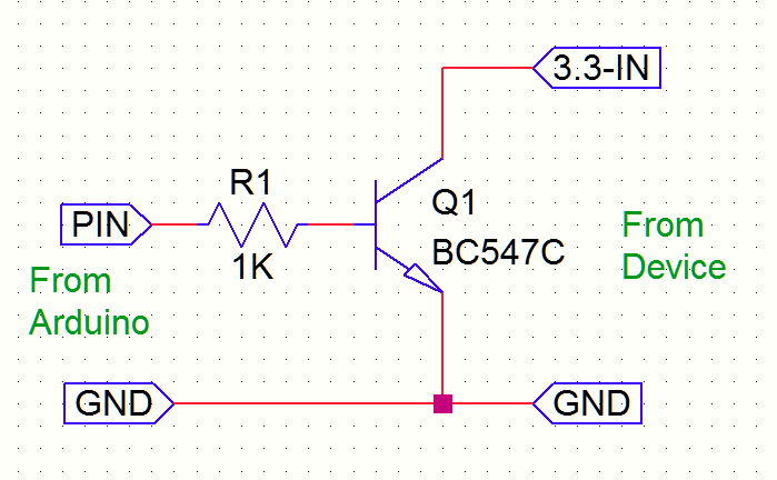
Ground cable should connect to the Ground pin on Arduino.
3,3V cable should connect to a digital pin on the Arduino and switch between pinMode(INPUT) and pinMode(OUTPUT) . When this pin is in output mode it will pull the voltage of the pin down to ground. I may put a 1K resistor between the 3,3V pin and the the Arduino in order to protect the Arduino while still ensuring it can pull the voltage down.
Is this completely bonkers or am I on the right track?
Hi Jim, thank you for replying so fast:)
I haven't tried connecting a 1K resistor, but if you think that 10K resistor would be a better option than 1K I will definitely try that.
So you think that the whole idea could work?
There are many ways of doing this. The simplest especially if you want isolation is to use a relay module. If you want to do it electronically use a MOSFET.
Ha can use a cheap, single channel optocoupler (as I remember, like an LTV815) too, if the switching frequency is like limited to a real ON/OFF pattern. That will provide real isolation.
That would be a good solution assuming there is not much current. Connect the opto emitter to ground, the opto collector to the 3V signal. The LED needs a few hundred ohms in series with it and then drive it directly with a port pin. I am assuming a UNO or other 5V Arduino.
That is why I recommended the optocoupler.
However, if I understood correctly it is a 3,3V signal pulled to GND.
With that, it is not needed to connect the two grounds galvanically.