I have built a timing circuit that I want to use to trigger a pulse on a Tig welder, everything is working except interfacing with the welder.
I just need to close 2 pins together on the welder which I measured has 12v across them, I found this thread, and I have connected a PC817 optocoupler as shown but It is not triggering. Am I missing something here?
I would like to keep the circuits as isolated as possible, I have a couple HW-532 mosfet boards which I took the optoisolator from, so can use that if needed.
The circuit as shown should work for its original purpose. It may not necessarily work for your purpose, since we have no idea how much current flows through that "12V signal".
We'd also need to see the code you are using to trigger the sensor.
Basically at this point we can't offer anything but guesses.
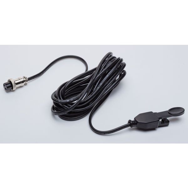
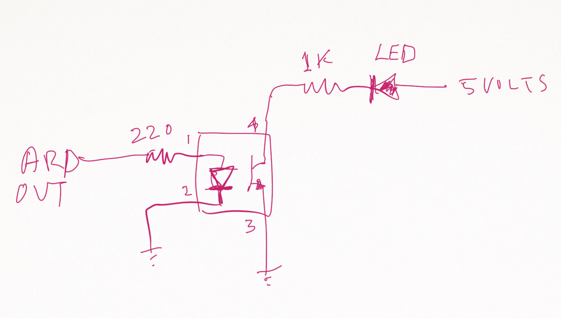
Thanks for the replies @TomGeorge@cedarlakeinstruments I have attached a circuit diagram, code and picture of a similar trigger button that I am trying to replace with the arduino.
#include <SPI.h>
#include <Wire.h>
#include <Adafruit_GFX.h>
#include <Adafruit_SSD1306.h>

#include <Fonts/FreeMonoBold12pt7b.h>

Adafruit_SSD1306 display = Adafruit_SSD1306(128, 64, &Wire);

// INPUT: Potentiometer should be connected to 5V, GND and pin defined below.
int potPin = A0; // Potentiometer output connected to analog pin 3
int potVal = 0; // Variable to store the input from the potentiometer

const int triggerSwitch = 2; // Connected to the trigger on the torch
const int gasSolenoid = 3; // Connected to the SSR which triggers the gas solenoid
const int weldOutput = 5; // Connected to the welder switch input

const int gasPreflow = 1; // Hard coded gas preflow time
const int gasPostflow = 1; // Hard coded gas postflow time

void setup()
{
    display.begin(SSD1306_SWITCHCAPVCC, 0x3C);
    display.setTextColor(WHITE, BLACK);
    pinMode(triggerSwitch, INPUT);
    pinMode(gasSolenoid, OUTPUT);
    pinMode(weldOutput, OUTPUT);
}

void loop()
{
  potVal = analogRead(potPin);                // Reads the value of the potentiometer (value between 0 and 1023)
  potVal = map(potVal, 0, 1023, 500, 1);     // Scale it to use it get the right time (value between 10 and 500)

  display.clearDisplay();
  display.setFont();
  display.setCursor(14, 5);
  display.print("Batt Pulse Welder");

  display.setCursor(28, 55);
  display.print("Milliseconds");

  display.setFont(&FreeMonoBold12pt7b); // Sets larger font for the number display

// Move curser based on number of digits to ensure the value is centred
  if (potVal <10){ // Single digits
    display.setCursor(54, 40);
  }
  else if (potVal <100){ // Double digits
    display.setCursor(46, 40);
  }
  else{ // Tripple digits
    display.setCursor(40, 40);
  }
  display.print(potVal);

  display.display();

  if (digitalRead(triggerSwitch) == HIGH){ // Trigger on the button press
        digitalWrite(gasSolenoid, HIGH); // Start the gas flow
        delay(gasPreflow*1000); // Mulitply the seconds to get milliseconds
        digitalWrite(weldOutput, HIGH); // Start the welding pulse
        delay(potVal); // Duration of weld pulse
        digitalWrite(weldOutput, LOW); // Stop the weld pulse
        delay(gasPostflow*1000); // Mulitply the seconds to get milliseconds
        digitalWrite(gasSolenoid, LOW); // Stop the gas flow

    }
}
Thanks to all for the responses so far, I swapped out the opto and changed the resistor to 1k which was what was on the HW-532 mosfet board that I took the opto off.
With the 220ohm there was a measurable signal but not enough to light an LED, I put the LED on pins 1 & 2 of the opto to make sure the arduino was outputting to the pin. It is working now, however it feels like the switch is 'soft' and when plugging in the normal switch trigger, it is a much stronger pulse. As I am writing this now I kind of realise that the 1k resistor is probable not the right value, and could be causing this 'soft' behaviour. I did test two different 220ohm resistors though so thats also quite weird.