I recently got a basic handheld oscilloscope, and I was playing around with it as a learning exercise.
I put together a low pass filter and used a PWM output from an arduino to get a square wave input.
I am using a 10 ohm resistor and a 10uF capacitor, so the cut off frequency is 1.6 KHz.
The frequency of PWM from the arduino is 490 Hz and its duty cycle is set at around 50%
I simulated the same circuit on Falstad so what I expected to see was the picture below. The cap charging up to the peak of the square wave and then discharging fully on the troughs of the square wave.
On the oscilloscope however, I see the capacitor charging and discharging but not fully, and the amplitude is lower than that of the input wave.
I have the display set to 1V per division
Initially I thought the filter is set up wrong and the signal is attenuated so the amplitude is lower, but 490 Hz is well before 1.6 KHz cutoff point, so it should not be attenuated yet.
Can someone tell me what I am doing wrong? Is using an Arduino as a signal generator wrong? Or maybe the handheld oscilloscope is just junk?
The source impedance of the Arduino Uno output pins is on the order of 40 Ohms(1), so your circuit is roughly 40 Ohms (output pin) plus 10 Ohms (resistor) and then the capacitor to ground.
The Falstad simulator square wave source is an "ideal voltage source" in that it is a voltage source with zero resistance whereas real world electronic components are "non-ideal". If you had a load resistance significantly larger than the output pin resistance, as is often the case, then the pin resistance can be ignored.
Note also, that with a low resistance load, the peak current (about 170 mA) of your circuit exceeds the absolute maximum rating for the microcontroller. It's unlikely to damage the part because of the internal resistance, but it is poor practice to exceed the part specification.
Thus an equivalent circuit, in the sense of frequency response, would be a 1k Ohm resistor and a 0.1 uF capacitor. Here the 1k resistor is more than an order of magnitude larger than the pin's output resistance, and limits the circuit's peak current to less than 2 mA, well within the device specification.
(1) The value of 40 Ohms is an approximation based on the figures in "31.1.8 Pin Driver Strength" of the Atmega328 Datasheet.
That won't work. With enough filtering you can get a (approximate) sine wave (with diminished amplitude) or you can filter PWM to its average DC voltage.
A square wave has high frequency harmonics (multiples of the fundamental frequency). To keep it "square" you probably have to pass up-to 4900Hz. In a true square wave (which doesn't exist in the real world) there are infinite-diminishing odd harmonics and the total energy in the harmonics equals the energy in the fundamental sine-wave component.
50'% PWM is a square wave, or any pulse through a type-T flip-flop will make a square wave with half the frequency so that should work with PWM too.
Thanks to everyone for chiming in. The point about impedance of the pin was spot on, when changing the resistance in the sim to 50 ohms, it was exactly what i saw on the oscilloscope.
I changed the components around like suggested and here is what i saw on the display, so all is good.
Thanks very much @MrMark for the thorough answer and explanation. It all makes sense now.
Could you explain how you got the value for current? I assume its calculated differently if there is a capacitor at play?
I used the formula Fc = 1 / (2 * Pi * R * C)
I am playing around with this as part of a car project.
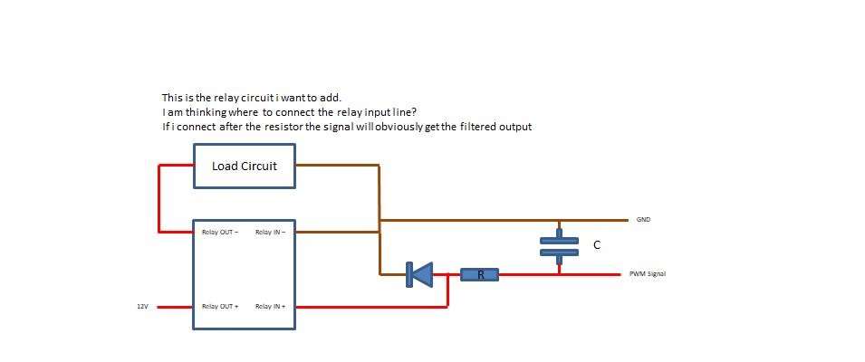
I want to use a signal to trigger a relay, but this signal is PWM so i am playing with caps to smoothen it.
There is an LED on that line already. I know that the duty cycle is used to control its brightness, but i hope that when a steady voltage (which is the averaged out PWM signal) is achieved, the brightness will not change by much. Then I am also wondering about the best place to tap into for the relay input side.
The few following pictures show my thinking and question:
I read the current off of the Falstad Simulator linked above, but mistakenly hat the square wave source going -5 to +5 Volts rather than 0 to 5 Volts, so the current is what I said above. For an instantaneous peak current, treating the capacitor as a short circuit gives an upper bound in this case.