oric_dan:
Wessricci, there have been a couple of dozen other people on this thread who have said exactly what you've posted, so the best advice is go back and read the thread, as long as it is. It's the same thing over and over.
First thanks for answering.
Yes friend, I've read these 35 pages 4 times just today. for here is the only place that ta talking about it, elsewhere only speak of Arducam .. Even more to me that I do not speak English, but I can not understand what to do in the camera, only thing I got was just hit the link of the camera not to burn any more .. What I do not understand is:
I have the Arduino Mega, which library of camera I download?
What change them and where change?
What code to use? I tried all there, but I tar mixing and missing something ..
And where the photos were saved?
It's the only missing part of my final project of college and did not think it would be so complicated.
oric_dan:
I realize you have a bad problem, but all that "I" can say is, these questions have all been asked and answered "many" times in this thread. Getting this camera to work with an Arduino is NOT easy. Maybe 5 out of 100 people in the thread ever got it to work, from what I can tell. There is a reason this thread is 35 pages long, and the same questions have been asked over and over. It's just not that easy to do, even with MrAduino's help. Read Roger Clark's last couple of posts.
If you're very pressed for time, you might try something else, like Arducam or cmucam. It will save you a lot of trouble and frustration. That's the best I can say.
Sorry, but really I'm not managing to do correctly, even looking at other answers.
Yes, I thought about the possibility of buying the ArduCam module, but where I live I can not find to buy, have to import, and the deadline for delivery in this case is long gone.
If you just need an image into an Arduino there are camera modules which produced JPEG and communicate with the Arduino via the Serial port like this one
If you could not compile it due to undefining haveSDcard the latest commit will address that issue. Also I have confirmed by means of testing using the code I updated that my camera module has endured no hardware damage and it still works fine. I still suspect a change in the way Linux, the kernel handles incoming serial data is causing me issues.
When I first saw your post I cringed a bit. However I decided to view your other posts and found out that you are a Spanish speaker. Since that is the case I now understand why you did not capitalize I. I do know that the word "yo" is lowercase in Spanish, however this is English and in English the word "I" is always capitalized. Quite a few native Romance language speakers make this mistake. Also of course there are lazy English speakers who perhaps contribute even more to the lowercase I problem.
The reason I am writing this is due to the fact that I fell more apt to answer questions with I capitalized as it should be.
You need to read the code first then if you think it is relevant ask. I was able to look at the code and find out that it is of little relevance. What I cannot understand about the code is why are they bitbanging SCCB? There is no need for that. Also this code will only tell you if your module is working and nothing more. It doesn't even setup the camera module to output a good image.
I'm so sorry to bother this thread, but; the lack of experience with working directly with avr-gcc, doesn't let me go further with this project. I installed WinAvr; ignoring if its the proper tool as I'm on Windows. Then I tried to compile (not upload yet) the ov7670 simple project, but I don't know whats the issue.
In CMD, the error goes as follows.
It appears you are using an old version of avr-gcc that does not yet support LTO. You can remove -flto and -fuse-linker-plugin or use a newer version of avr-gcc. However note that not using LTO may result in suboptimal generated code.
Yes of course. First of all what hardware are you using? That will determine the framerate you are able to get. Also I have developed a much faster way to grab pixels but it misses the first byte unfortunately. I ran the ov7670 at 24mhz and was outputting QVGA video at 8mhz (since the resolution is 1/4 of VGA it outputted pixel data at 1/4 the speed). After waiting for PCLK to rise in a loop I then enabled PWM on a TFT data line and then made an unrolled loop that send the pixel data 640 times (there are 2 bytes per RGB565 pixel that is why 640 instead of 320). This means I got 30fps on an Arduino Mega. It was very fast.
I am using a parallel LCD. What happens is the WR data line must be toggled for each byte. What I do is first wait for PCLK and then just copy port values without any delay then disable PWM after one line has been transferred. I do this for 240 lines since the resolution is QVGA. You could do a similar stagey for SPI ram, you would just need to run the ov7670 at a slower speed and add some NOP instructions per pixel. Here is the code. I would really like it if someone could solve the off by one byte problem. I have done a lot for you guys and would really like to it if you could help get me unstuck just as I have done for many of you guys.
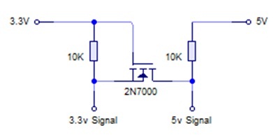
I'm using a voltage divider to change xclk level but it's slow and I want to switch to a faster and cheap solution, so I'm using this bidirectional level shifter to convert xclk to 3v3
but my clock looks like this and the module doesn't work (yellow before conversion and blue after conversion)
does anyone know why the converted signal looks so unrelated to the original?
edit: I figured out that scheme should be specific for i2c and resistors are not part of the level converter; so I plugged the xclk in the gate, 3v3 in the source and the drain to the ov7670 and it looks like it's working
how could I fix that? could get better performance with bss138 instead of using 2n7000? can anyone confirm my assumptions? Is what I'm doing safe/correct?
p.s. I hope I'm going to release the program you see in the image soon under MIT license (open source) on github. It's written in C# and aims to display and record camera stream in real time from serial and change registers runtime. (it's based on Mr. arduino's work!!!)
If you desperately need it I could release it now but it lacks most of the feature, decoding it's buggy (strange random gray splotches) and the code struggle for refactoring XD
Hello,
sorry to may be ask a stupid question, but would like to use the ov7670-simple-master projet but there is no .ino which is the only think that I ever used. So please, how this projet is meant to be used ?
yours sincerely.
EvIl_DeViL:
I'm using a voltage divider to change xclk level but it's slow and I want to switch to a faster and cheap solution, so I'm using this bidirectional level shifter to convert xclk to 3v3
but my clock looks like this and the module doesn't work (yellow before conversion and blue after conversion)
does anyone know why the converted signal looks so unrelated to the original?
edit: I figured out that scheme should be specific for i2c and resistors are not part of the level converter; so I plugged the xclk in the gate, 3v3 in the source and the drain to the ov7670 and it looks like it's working
how could I fix that? could get better performance with bss138 instead of using 2n7000? can anyone confirm my assumptions? Is what I'm doing safe/correct?
p.s. I hope I'm going to release the program you see in the image soon under MIT license (open source) on github. It's written in C# and aims to display and record camera stream in real time from serial and change registers runtime. (it's based on Mr. arduino's work!!!)
If you desperately need it I could release it now but it lacks most of the feature, decoding it's buggy (strange random gray splotches) and the code struggle for refactoring XD
I'm not a expert in eletronic, but maybe there is some detail in the use of 2N7000 that makes it not properlly for use in a clock circuit.
Some diods in serie wouldn't fit for the purpose?
@Flaviold: I saw some sparkfun level converter using bss138.
The only difference I can think of is about the gate activation threshold which is lower (better) on the bss138 which is 1.3V versus the 2.1V of the 2n7000 (I'm going to buy 'n try those).
This could be the cause of the noisy/uneven wave you see in my clock signal.
You shouldn't use diodes to step down signal levels because at such high frequency and low voltages a lot of factors come into play (hysteresis, parasite currents, dispersion and... I don't know what else but surely there's other nasty stuff). It will be worst!
I'd like to use passive components avoiding buffers, mainly because they are cheaper and they look more professional to me.
I've being studying electronics for about six month and what I learnt is that is all about missing the right component in every single project you begin XD
@Mr-julien: I use windows, visual studio and the visualmicro plugin. Arduino IDE cannot manage multi-files projects so you should move on if you want to grow up If you REALLY want to grow up you should try atmel studio which is the official atmel IDE and integrate it with arduino's toolchain (It's on my todo list also...)
@EvIl_DeViL:
Interesting notes on the use of diodes. Like I said before, I'm not a expert on electrocnic. So, what I know is what I read on the internet.
I have not tried diods yet. I have the OV7670, circuit (with diodes) and Arduino ready to be turned on. But now I think it's better to wait and look for another solution to the clock source question. An external clock source, for example.
If you have success, please show your solution here for us.
Best regards.
many solution has been proposed for this matter:
mr arduino uses a 74AHC125 buffer, I used a voltage divider (which work but is slow), I tried a 2n7000 with a little luck, and now my bss138 are on their way to my home to test this other solution which should be cheaper but as a matter of facts mr arduino's 74AHC125 is the only stable and cheap solution for the clock issue for now a clock generator would be cooler but more expensive than the right transistor which, I believe, do exists. Bonus: a good transistor can be re-used for other signal converting issues; a clock generator is suitable only for this specific case (generating a clock).
I'm posting to say I2C scanner on DUE it's working here!!! I'm moved! T______T You need to use SCL1 and SDA1 with 1K pullups and use Wire1.* instead of Wire.* (for example Wire1.begin(); ) in your code because in DUE's SDA and SCL pins have a 10K pullup and you can't disable them! I hope everything will be smooth from hereafter
I should have read somewhere, if I'm not mistaking, that the lowest safe limit for I2c's pullups on DUE is 220ohm because 3.3v/220ohm = 15mA (?!?) this should pull much faster o_o it's true/safe/useful?
seriously? I answered this question to Mr-julien just 4 post ago! I know this is a long thread but guys please read at least the first 5 and the last 5 pages... this thread was opened from Mr.Arduino to improve and share his knowledge but keep answering the same questions every three posts took out his excitement for this project (I'm not referring to you only) and this breaks the chances for all the community to make progresses on this topic!
Lets keep this thread cooperative and fruitful ok?