I am wondering if it is safe to drive the base resistor of a single transistor connected to two seperate output pins of two different Attiny85 microcontrollers.Each output pin will be controlled via a switch input (one switch for each output).Hope this makes sense.
Thank You all guys for your response, was thinking that maybe the two base resistor method was OK, but the two diodes solution seems to be the answer, appreciate your advise.
Paralleling output pins is only sensible if you use direct port manipulation and the pins
are on the same 8-bit port, and if the sketch always switches them in unison - so it
can be done, but with care. All 8 bits of a port are updated on the same clock edge
when a port is written (ie PORTD |= 0xF0; sets D4 to D7 on the Uno for instance)
MarkT:
Paralleling output pins is only sensible if you use direct port manipulation and the pins
are on the same 8-bit port, and if the sketch always switches them in unison - so it
can be done, but with care. All 8 bits of a port are updated on the same clock edge
when a port is written (ie PORTD |= 0xF0; sets D4 to D7 on the Uno for instance)
I must see the first direct port manipulation that works on two independent micros at the same time
I'm not yet familiar with direct port manipulation, alot to learn but am enjoying the challenges that my project are throwing up.My concerns were sending 5v to an output pin but the diode solution was or seems to be the answer as i have breadboarded this option and it works.
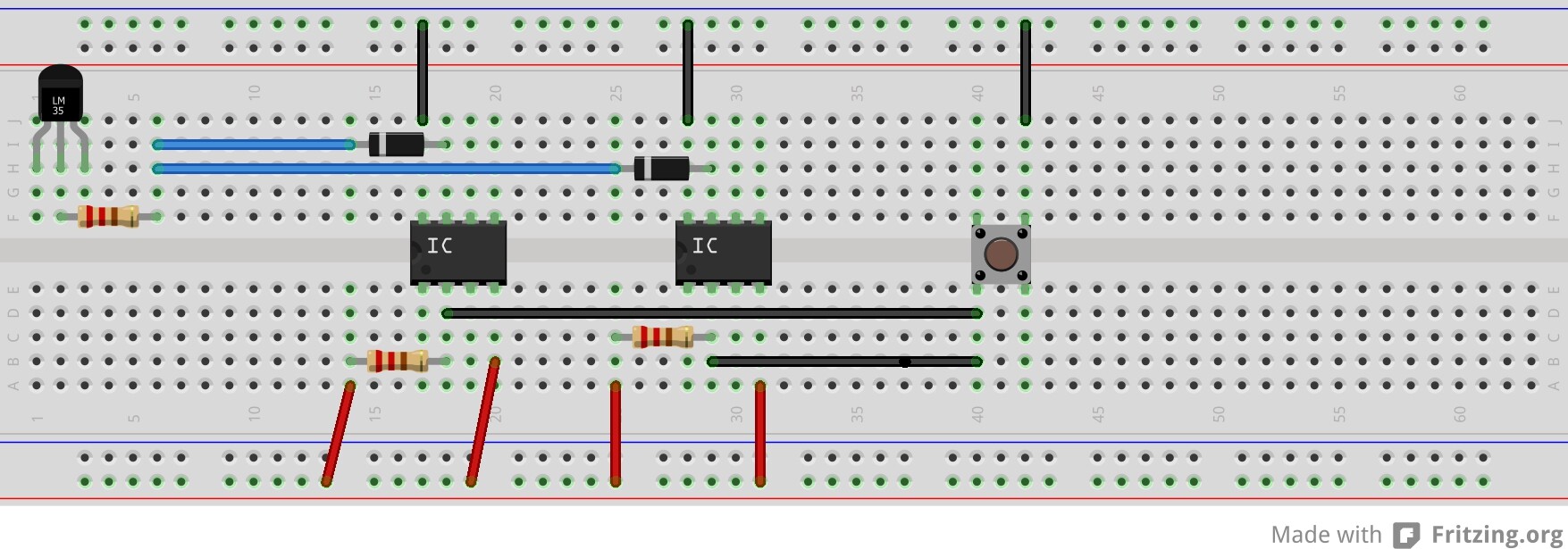
Sorry i posted the wrong schematic, the correct one attached will be switching two different loads from a single switch and i'm just curious to know if it is safe.