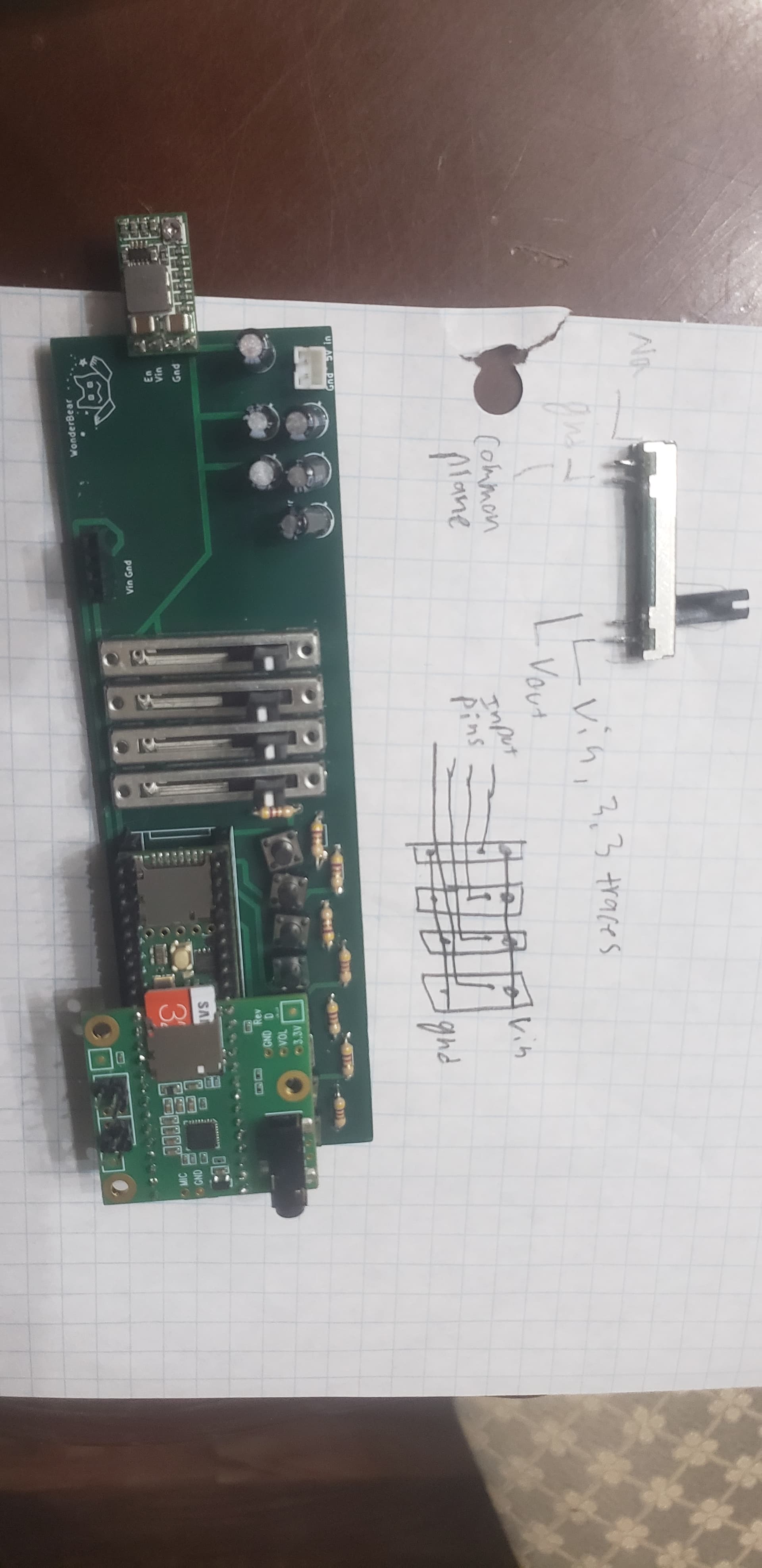
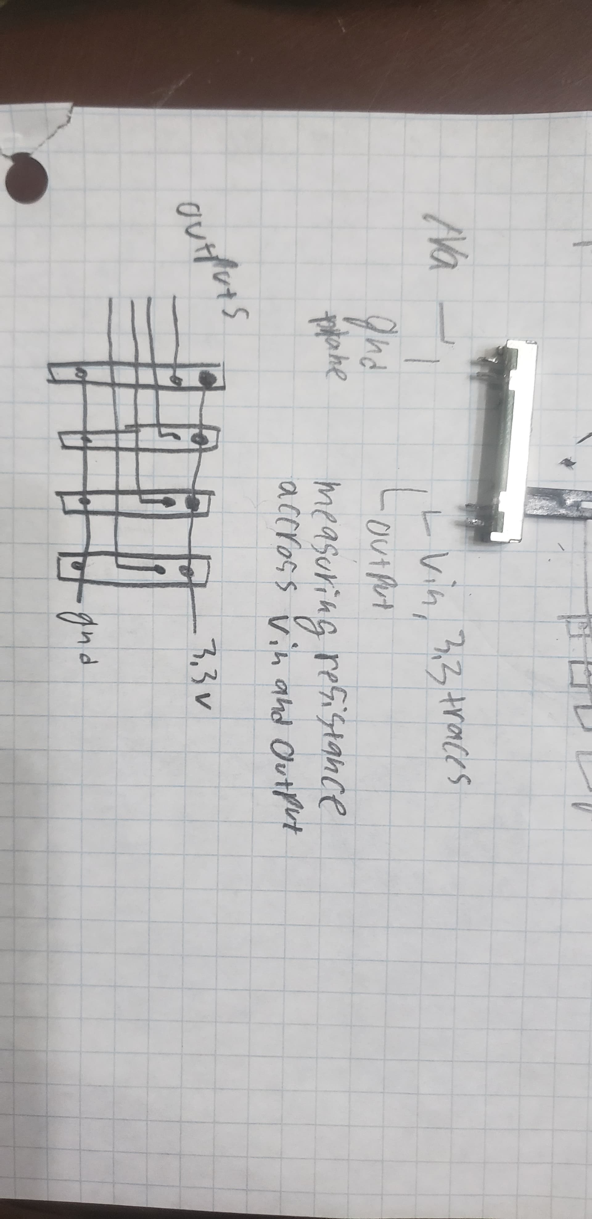
Hello. I have 4 potentiometers on a pcb, whose grounds are common and power are common. When i measure the resistance of each potentiometer, they start low, climb to max at the middle, then fall back down. When i measure a similar potentiometer on its own, it is linear and grows.
According to this forum, they should work fine
I have very little clue what I'm doing, what do you think could be the issue?
I'm assuming that the power is off when you make the measurements, is this correct?
You can consider that the power supply +ve and -ve rails are close to short circuit, or at least a low value resistance between them, so if the pots are connected to the power supply as you describe then for the purposes of the test the ends are connected together, giving the results you found.
I've tried two different multimeters and they had the same behavior.
In the pcb, at the top they were 60 ohms, .25 of the way down they were 7.5 k ohms, half way they were 14.5 k ohms, .75 of the way they were 13.8 k ohms, and all the way down they were 9.1 k ohms
I desoldered a pot, it works normally.
at top: 2 ohms
.25% down: 7.5 k ohms
.5% down: 23.9 k ohms
.75% down: 37.7 k ohms
full down: 45.1 k ohms
compared to when the same one was in the pcb:
top: 60 ohms (close)
.25%: 7.5 k ohms (same)
.5%: 14.5 k ohms(much less then outside)
.75: 13.8 k ohms (decreasing more)
down: 9.1 k ohms
You said you measure while power is off. It seams that in that condition there is a connection of 9.1 k between ground and power. That explains perfectly the behaviour you observe.
Your 4 pots are in parallel with each other, plus the other circuitry on the board. There is a low resistance between the ends while they are in the board.