I am trying to get started using these PWM driver expansion boards.
I noticed that many purchasers of the same board -
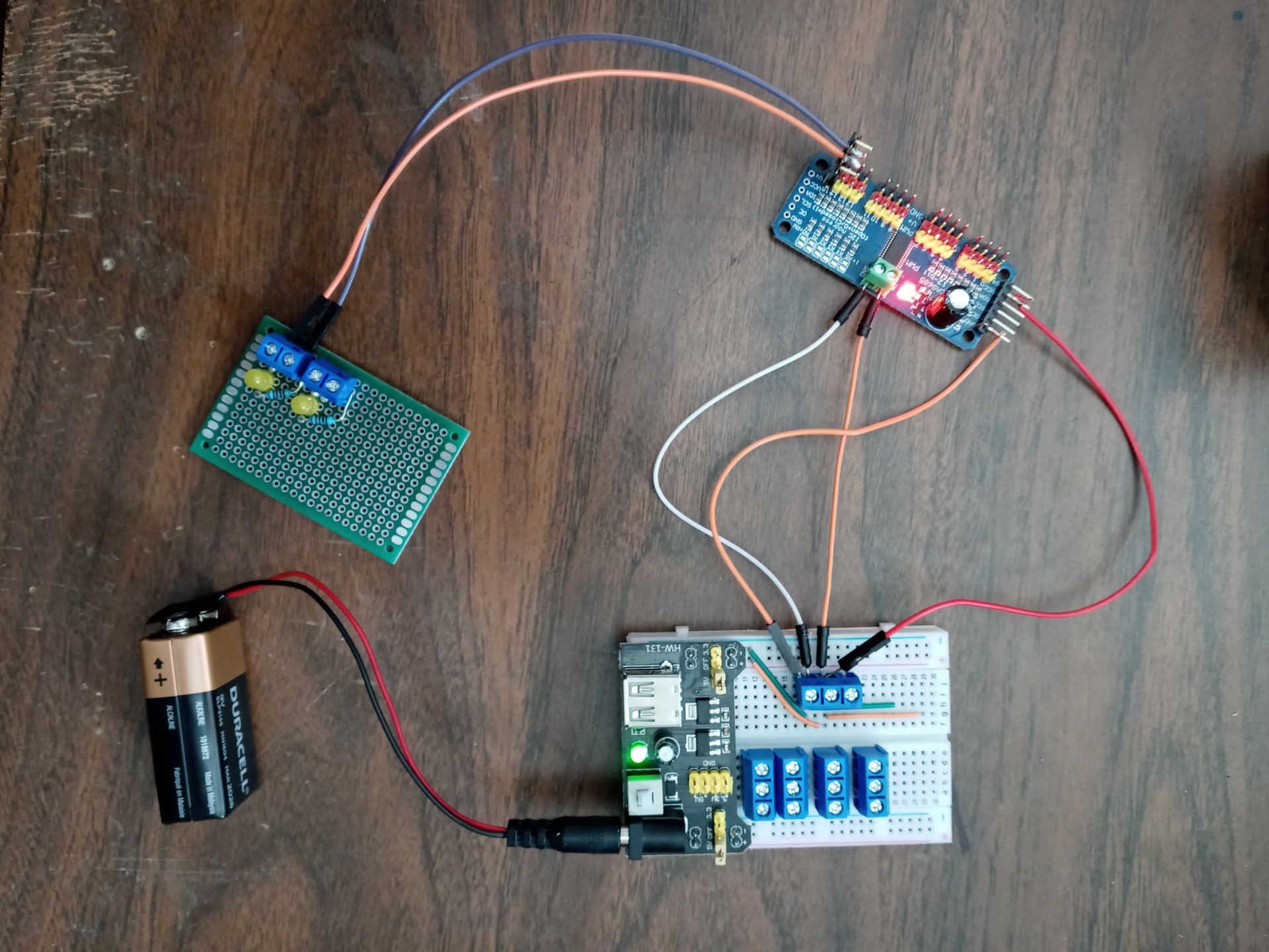
stated in reviews that the green plastic screw terminals for power/ground were not working.
Upon testing the terminals on the pca9685 boards that I bought once they arrived, I was not able to get the power indicator LED to light up when I applied the needed 5 volts. I assumed that this was the problem being complained about in reviews. Is the power LED supposed to light up from the V+/Gnd screw terminals being hooked up? I applied 5v/Gnd to the Vcc and Gnd pins on the left side of the board, and the power LED lit, but this is stated as only powering the chip, not the actual 16 outputs, as others have stated in reviews.
PS - the output powers and grounds (the red and black pin header rows) are supposed to be live when the board is powered, right?
I would greatly appreciate any advice from someone with experience using these products.
But with a proper power source and if the Arduino was integrated then I suppose it should.
You're doing some desperate wiring twisting there which can result in profound unhappiness.
The 9V battery is powering a 5V breadboard power supply. I tested the setup again bypassing the screw terminal and just using the 90 degree pin header's V+ on the right side end of the board. It works now. I suppose if I want to use the screw terminals I will just have to bodge wire the back of the board. Thank you for your help.
When I apply 5V (B) at those big pads I then see that at the servo terminals and the V+ points on the SIP rails. (This 5V passes through a PFET, so there isn't 0ohms from the V+ terminal to "V+" on the SIP rails.)
When I apply 5V (A) at VCC, the onboard LED turns on.
