16-channel, 12-bit PWM Fm+ I2C-bus LED controller


It is attached to a mega. SCK and SDA.
Connections are correct as I2CScanner sketch shows device at 0x40.
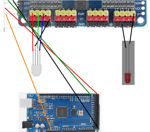
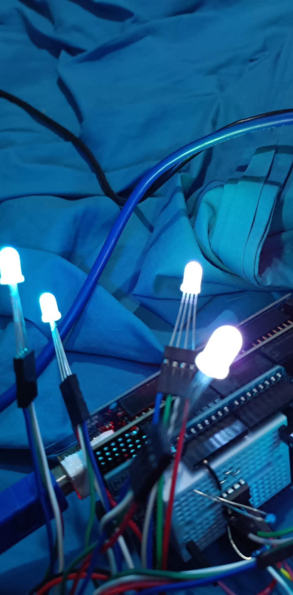
I have 5 x common anode RGB LEDs connected plust 1 x ordinary red LED.
RGBs are connected to 5V and channel.
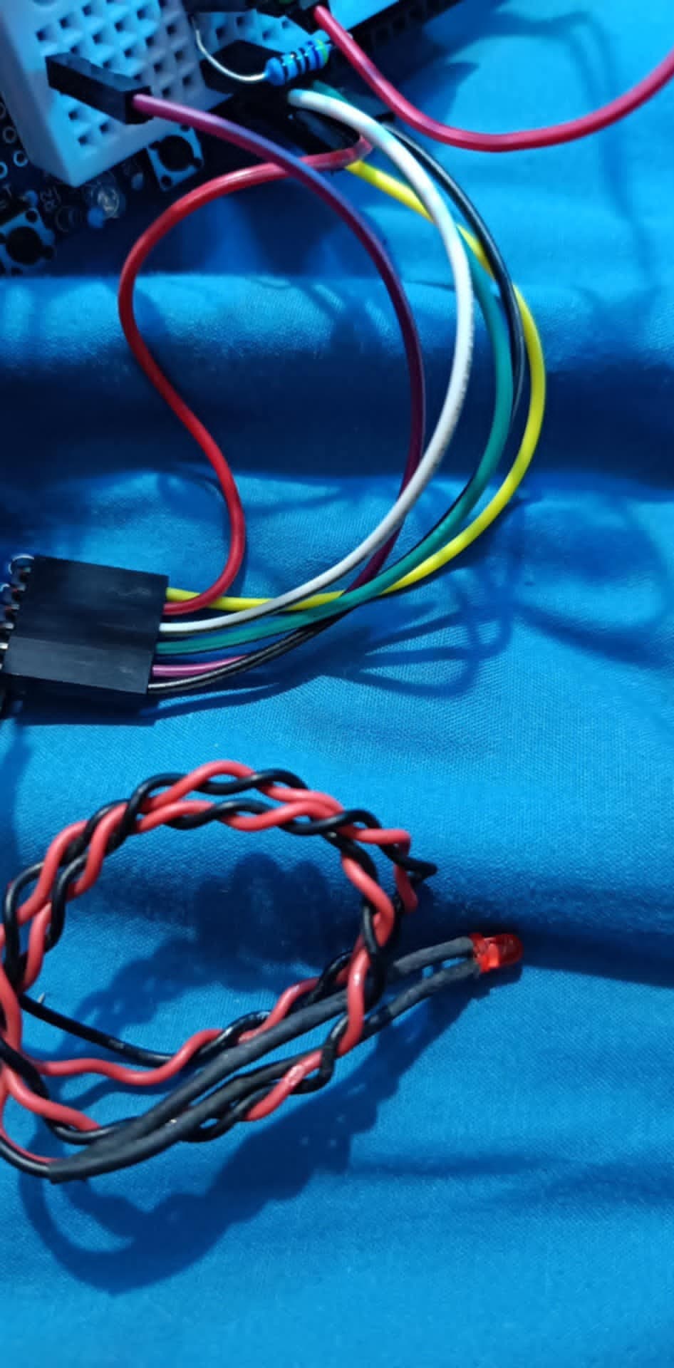
Red LED is connected to GND and channel.
The RGB LEDs won't turn off and the red LED won't turn on.
I have slightly modified the example sketch:
/***************************************************
  This is an example for our Adafruit 16-channel PWM & Servo driver
  GPIO test - this will set a pin high/low

  Pick one up today in the adafruit shop!
  ------> http://www.adafruit.com/products/815

  These drivers use I2C to communicate, 2 pins are required to
  interface.

  Adafruit invests time and resources providing this open source code,
  please support Adafruit and open-source hardware by purchasing
  products from Adafruit!

  Written by Limor Fried/Ladyada for Adafruit Industries.
  BSD license, all text above must be included in any redistribution
 ****************************************************/

#include <Wire.h>
#include <Adafruit_PWMServoDriver.h>

// called this way, it uses the default address 0x40
Adafruit_PWMServoDriver pwm = Adafruit_PWMServoDriver();
// you can also call it with a different address you want
//Adafruit_PWMServoDriver pwm = Adafruit_PWMServoDriver(0x41);
// you can also call it with a different address and I2C interface
//Adafruit_PWMServoDriver pwm = Adafruit_PWMServoDriver(0x40, Wire);

void setup()
{
  Serial.begin(115200);
  Serial.println("GPIO test!");

  pwm.begin();
  pwm.setOutputMode(false);
  pwm.setPWMFreq(100);
  //pwm.setPWMFreq(1000);  // Set to whatever you like, we don't use it in this demo!

  // if you want to really speed stuff up, you can go into 'fast 400khz I2C' mode
  // some i2c devices dont like this so much so if you're sharing the bus, watch
  // out for this!
  //Wire.setClock(400000);
}

void loop()
{
  static uint16_t nPWM100 = 4096, nPinState = nPWM100;

  // Drive each pin in a 'wave'
  for (uint8_t pin=0; pin<16; pin++)
  {
    pwm.setPin(pin, nPinState);       // turns pin fully on
  }
  Serial.println(F("=================================="));
  if (nPinState == nPWM100)
    nPinState = 0;
  else
    nPinState = nPWM100;
  delay(1000);
}
Library debug output turned on:
GPIO test!
Attempting to set freq 1000.00
Final pre-scale: 5
Mode now 0x0
Setting output mode: open drain by setting MODE2 to 0
Attempting to set freq 100.00
Final pre-scale: 60
Setting PWM 0: 4096->0
Setting PWM 1: 4096->0
Setting PWM 2: 4096->0
Setting PWM 3: 4096->0
Setting PWM 4: 4096->0
Setting PWM 5: 4096->0
Setting PWM 6: 4096->0
Setting PWM 7: 4096->0
Setting PWM 8: 4096->0
Setting PWM 9: 4096->0
Setting PWM 10: 4096->0
Setting PWM 11: 4096->0
Setting PWM 12: 4096->0
Setting PWM 13: 4096->0
Setting PWM 14: 4096->0
Setting PWM 15: 4096->0
==================================
Setting PWM 1: 0->4096
Setting PWM 2: 0->4096
Setting PWM 3: 0->4096
Setting PWM 4: 0->4096
Setting PWM 5: 0->4096
Setting PWM 6: 0->4096
Setting PWM 7: 0->4096
Setting PWM 12: 0->4096
Setting PWM 13: 0->4096
Setting PWM 14: 0->4096
Setting PWM 15: 0->4096
==================================
OK so the channels are toggling according to the debug output from the library.
But there is no effect on the channels apparently because there is no change in the LEDs.
Has anyone used this library with LEDs successfully.
How did you get it working?