I recently finished designing a PCB for my project, which aims to monitor industrial electric motors by logging data such as motor temperature, current, and vibration. I'm hoping to get some feedback from the community before moving into the production phase.
Here is a quick overview of my project:
Sensors: I am using an ADXL345 accelerometer, an MCP9808 temperature sensor, and a JST connector for a current sensor.
Microcontroller: I chose an Atmega328p-au to compile and send the data.
I2C Multiplexer: To increase the number of I2C ports, I added a TCA9548APWR to the project.
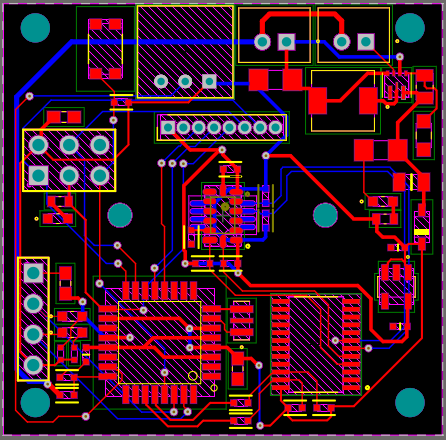
RF Transmitter: Data is sent through an RF transmitter connected to the pins of the J2 connector.
Power system: I am using a power voltage circuit to increase the battery voltage from 3.7V to 5V for the Atmega and other 5V components, and an LDO voltage regulator to convert to 3.3V for the RF transmitter.
Protection: A diode is placed at the output of the supply voltage to prevent a 5V voltage from entering the system in the opposite direction when using the UART and ICSP connection pins.
Connectors: JST J3 connects the battery, and J4 is a switch to turn off the system.
I would really appreciate it if you could take a look at my PCB design and give me feedback on any possible errors, such as short circuits or incorrect components. Also, any general suggestions for improvements or changes that could be made to the design would be super helpful.
Why?
I2C is a bus. In theory up to 127 devices can be connected to the same two pins, as long as they have different addresses.
The TCA provides level conversion for that 3.3volt device, so that must be added if the TCA is removed.
Leo..
This is the battery input, output A3 is for measuring the battery level, and J4 is a switch.
But actually I think that this system of measuring battery will not work in this case. It was for a 7.4V battery but for a 3.7V battery it doesn't make much sense.
They are large and medium-sized industrial engines.
This system is connected by magnets to the engine and sends the data to a central that later sends them to an HTTP server.
I wanted to give you an update on my PCB design since I've made a few changes based on previous suggestions and research.
Removed Components: I've removed some components that were not necessary for the current design.
Battery Percentage Measurement: I've added a MAX17048G to measure the battery percentage, which is now connected to the TCA9548APWR.
Bypass Capacitors: I've included additional bypass capacitors in the design.
Atmega Bypass: I separated the bypass capacitors for the Atmega, but I'm wondering if this is necessary. Can I use a single bypass capacitor for multiple pins of the same component, or is it better to keep them separate?
I'd appreciate any thoughts or advice on these changes, especially regarding the bypass capacitors for the Atmega. Thanks again for all your help and support!
It's a little early for me still, but I'm not quite catching what you're saying.
Where will the analog signal be coming from? What type of current sensing device exactly do you plan to use? This is important because you may have minimally exposed wires, if at all, making clamps difficult to attach and having something in series with the wiring has considerable difficulties as well. Most motor controllers already monitor the current draw so it would be redundant. If you can measure the phase to phase voltage difference that could be potentially beneficial because it can indicate internal wiring degradation. That would likely also be measured at the controller and redundant.
I don't want to poo poo your project but I do want to make sure you take into account things like EMI's effect on your radio transmission as well as signal congestion when used in large quantities.
Why are you designing a pcb when you're still finalizing the schematic?
Sounds like the design spec isn't complete.
Build one with point to point wiring and make sure it works, and only THEN design a pcb.
I have some experience designing monitoring systems for electric motor driven compressor systems. I'm curious to know if you intend to provide any mechanism to shut the motor down in case of some anomaly and what, if anything, these motors are driving.
I'm actually deciding to keep the JST, but use it as a separate circuit connection that will have the main purpose of monitoring the current and other electrical parameters of the motor. Something external and that has this only function since apparently I will need something very robust for this type of motor.
The differential of my system will not only be to measure and display the data to the engine operator, but to correlate the data and create plans for predictive maintenance of the engine. Therefore, measuring the current gives me the possibility of correlating this data with the temperature, for example, and locating electrical faults more effectively.
I didn't understand very well, how could I do that ?
I have this concern too, the main idea is to use bypass capacitors besides trying to put some kind of shielding made of conductive material in the capsule that holds the circuit.
My mistake, I was a bit hasty.
The first idea is just to generate messages and log the anomalies in general, but in a second moment I intend to start developing these protection systems further to automate them in conjunction with this project.
I suggest you get in the habit of consistently calling them motors. Depending where you go you might be considered a real rookie if you call it an engine.
Be sure to consider that eventuality now in your initial design phase so you don't paint yourself into any corners.
The diode prevents signals coming from the 5V of the UART or ICSP from coming back into the boost converter. When I record the atmega I want the USBasp to power the circuit.
I am using the TCA9548 because I already worked with it before, I already have the code with it, so for me it is easier.
Surely you are joking. For a much-needed expansion of your horizon, and to avoid further embarrassment, look up the essential topic "power supply decoupling".