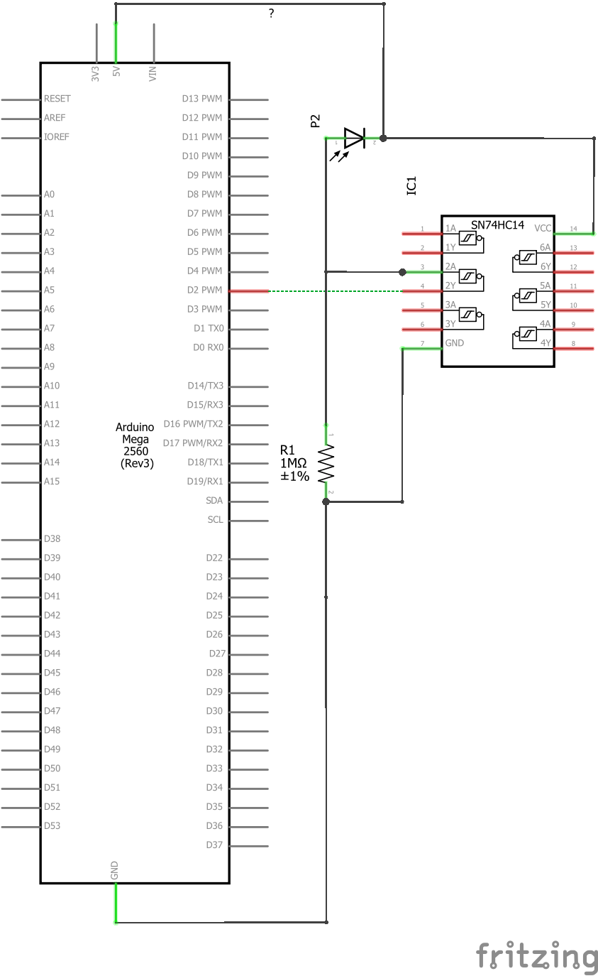
Currently developing a project using a Photodiode BPW34 and a Schmitt Trigger 74HC14, where light pulses hit the photodiode generating an interrupt, mostly of the system works, but there is a high probability of the below thing happens.
As can be seen, there is two interrupts at the same timestamp, one of them is expected, but the other not, and since i do not have an oscilloscope, verifying my hypothesis is very hard.
How can i prevent it?
Have tried:
120pF Capacitor connected with photodiode and Schmitt input ( Made the problem worst, but returned at the original problem when using 680K).
680K Resistor ( currently using an 1M, that generates around 5.1V when photodiode is fully iluminated, and around 0.25V when at ambient light).
Internal INPUT_PULLUP.
Reduce the time between pulses.
The code is a simple function that reads a value, save, and print it when a light beam hits the photodiode, through an interrupt. (Falling Edge)
Observation: Schmitt Trigger outputs 5V when no light is present at photodiode.
Please use better diagram than Fritzing. That's the info from ignorant sales people.
If my memory is ok the output of a HC14 is "open collector" and they only make a logic low, not high. A pullup resistor is needed. By the way, why involve that HC14 at all? You can use ana analog input and using software create any hysteresis You want.
jremington:
Please post the code, using code tags. Also, avoid Fritzing diagrams. A hand drawn schematic is much better.
Ok, working on it.
Railroader:
Please use better diagram than Fritzing. That's the info from ignorant sales people.
If my memory is ok the output of a HC14 is "open collector" and they only make a logic low, not high. A pullup resistor is needed. By the way, why involve that HC14 at all? You can use ana analog input and using software create any hysteresis You want.
Added to the post, using it because i need interruptions, and to use interruptions a digital input is needed, i could use analog, however it involves more code logic, and since the application is a critical one, tryin to avoid for a while.
Also, unfortunately i not an electronics expert.
Sorry but I don't know the expression "need interruptions".
Being a software designer, and often a hardware designer, the rule is: Software never brakes down. What can be done in software, do it, and don't use hardware.
Thanks for the drawing. I hope it is wrong. Nothing is pulling the 2A input of the HC14 and the open collector output, 2Y goes to digital I/O D2. That's not doing anything good.
I don't know about any 74' Schmitt triggers with open collector.
A low pass RC filter would consist of a resistor from the diode to the trigger gate and a capacitor from gate to Gnd.
Probably not. Use of interrupts usually causes more problems than it solves.
With ICs like the 74HC14, you should never leave unused circuit elements with open inputs. They will float, and the gates sometimes oscillate wildly. Always connect unused gate inputs to a known reference, like ground. You also need a 100 nF ceramic bypass capacitor across the HC14 power and ground.
You may be better off leaving out the HC14 entirely.
Also, if you have a spare 0.1µF capacitor, I would install it from the output of the BPW34 and GND. This will give about 0.1 sec time constant. Without it, the circuit will be very sensitive and prone to high levels of noise. The capacitor shouldn't affect the signal level per light level. May not need the 74HC14 if this resolves the problem.
Photodiodes are astonishingly fast so its no surprise you are getting multiple interrupts.
I'd suggest you use an RC filter to slow the response a little. Your 1M resistor will be fine, just choose a suitable capacitor - eg a 1nF will give you a 1msec time constant which would be a good starting point.
You need the schmitt to buffer the photodiode circuit as a digital input does not have a sufficiently high resistance.
In my use of the BPW34 photodiode, (with ESP32) I found that the photodiode produced the best output when it was reversed biased and used with a 1M resistor. I tied the cathode to 3.3V's, the anode to a 1M resistor that went to ground. I picked off, for AD, at the photodiode/resistor junction. My application allows an array of solar cells to follow the sun.
TomGeorge:
Hi,
Welcome to the forum.
What is the application that needs interrupts?
Tom...
Is a try to make a weird optical fiber receiver, when a light pulse clock is detected, i read a sensor at the moment of a falling edge, i thought that interrupts were suitable to an application where i can't afford to lose information.
johnerrington:
Photodiodes are astonishingly fast so its no surprise you are getting multiple interrupts.
I'd suggest you use an RC filter to slow the response a little. Your 1M resistor will be fine, just choose a suitable capacitor - eg a 1nF will give you a 1msec time constant which would be a good starting point.
You need the schmitt to buffer the photodiode circuit as a digital input does not have a sufficiently high resistance.
I tried using the capacitor (120pF and 470pF) as the same as in this topic (Schmitt trigger questions - General Electronics - Arduino Forum), with the Schmitt Trigger input, perhaps are you suggesting connecting a capacitor with the Schmitt input and output?
Bad idea to try serial I/O in an interrupt routine. It usually just hangs (Arduino is an exception). Set a global flag and leave printing to the main loop. Also, do not disable/enable interrupts within an interrupt routine.
I tried using the capacitor (120pF and 470pF) as the same as in this topic (Schmitt trigger questions - General Electronics - Arduino Forum), with the Schmitt Trigger input, perhaps are you suggesting connecting a capacitor with the Schmitt input and output?
No Scmitt input to ground. How fast are your pulses? I'd try a 2200pF - and as JRemington says, sort out your code.