Hi!
I'm working on a project in which I'm using E3JK-R4M1 with reflector, 24V power supply, LCD and ESP32 Wroom 32D for detecting and counting the boxes within a tunnel and show display on LCD. I've used ESP 32 wroom 32D for serial communication to my PC. Also, I used a push button to reset the counting on LCD.
The problem that I'm facing is auto-counting on LCD, even sensor detects nothing. I'm not sure, whether the issue is in LCD or Hardware connections or coding.
Please help me.
Hi news123,
welcome!
How somebody should be able to help, with this information?
No code.
No wiring diagramme.
No information about the LCD.
No information about what was already tested, what is working, what is not working.
Please raed this:
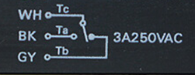
Relay output: 250VAC3 A (cosϕ=1) max., 5 VDC 10 mA min
So your load resistance need to be less than 500Ω with a 5V supply
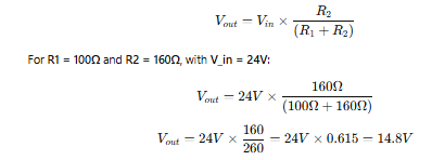
If you use it with an ESP, you will need to create a voltage divider
I would use a 100Ω and a 160Ω
when BRN is connected to +24V, then Vin is 24V. how these mentioned resistors will provide 3.3V with Vin 24V. I didn't understand this. Also white wire will be connected to GND or 5V of ESP 32 wroom 32D. Please explain.
Thankyou for your help.
please help in understanding the resistors that you mentioned: 100 ohm and 160 ohm, to convert 24V to 3.3V. with Vin =5V, the step down voltage will be 3.08V not 3.3V (to be used on ESP32). should not I use resistors that give exact step down 3.3V.
First you need to post your code so that it is readable
In the IDE click on File then copy for Forum, that will copy your code for the Forum.
Then come back here and do a paste.
To test the sensor operation I would just start with some very simple code to see if you can read the sensor pin and if it changes state when you break the sensor beam.
Just do a digitalRead and print it to the monitor
Hey @jim-p
I don't have 160 ohm resistor. I have 4.7k, 6.8k, 330, 470, 47k, 100k, 47, 220, 2.2k, 1k, 100, 10k, 22k, 10, 220k resistors.
Please guide, which any of two can I use among above mentioned, to get 3.3V or closer.
#define SENSOR_PIN 16  // GPIO pin where the sensor output is connected

void setup() {
    Serial.begin(115200);  // Start serial communication
    pinMode(SENSOR_PIN, INPUT);  // Set sensor pin as input
}

void loop() {
    int sensorState = digitalRead(SENSOR_PIN);  // Read sensor state
    Serial.print("Sensor State: ");
    Serial.println(sensorState);  // Print state to Serial Monitor
    delay(200);  // Small delay for readability
}