So I'm working on a project which has components/shift registers/ICs that all run on 5V logic and the minimum logic high voltages for all of them are higher than the 3.3v output that the Nano 33 IoT can supply. This is something I should've checked, to see if my main microcontroller can work with said logic levels, but it's a lesson learned. I already have my PCBs delivered to me, so it would be pretty expensive to make design changes to include level shifters at this point.
Is there any other Nano board that is pin compatible with the 33 IoT and has WiFi but is capable of 5v input/output via its digital pins?
I very much doubt that you will find such a board. The nearest alternative, albeit without WiFi is, of course, the classic Nano. Could you implement WiFi as a daughter board to your PCB ?
I am surprised that you went to PCB without testing the project hardware and software first
Ah, that's unfortunate.
Hmmm possibly. I'm not sure if any kind of external shield exists that gives the classic Nano wifi capabilities.
Regarding the PCB, it was tested before, but my mistake was assuming that the classic nano had the same logic levels as the IoT one. The project I'm working on is to make a clock, and the wifi bit is really only needed to read the current time from an NTC server periodically.
When I used the classic version, I would manually input the current time initially, and then let it run on its own (since there was a separate RTC IC on board that would retain the time once it was initially input)
ESP-01 modules are often used for this purpose. However, ESP-01 is also a 3.3V device which means you need 3.3V-to-5V level shifting between the Nano and the ESP-01 and that the Nano's 3.3V pin cannot supply sufficient power for the ESP-01, so an external regulator is required.
11.2 Pin Voltage
All digital & analog pins on the Nano ESP32 are 3.3 V. Do not connect any higher voltage devices to any of the pins
as it will risk damaging the board.
Small Esp8266 devboard like D1 mini?
It has 5v to 3.3V regulator and 3.3V signal from the Esp tx pin should be high enough for the nano to get the time data.
Ah, so it's a development board of its own with WiFi, and since it has an internal regulator, it could solve that issue, true. It's an option alright, even if it would be a somewhat hack fix.
Thanks! I'll look into it!
If you can tell the forum a little more about the PCB and components, that would give more scope for suggestions.
For example, there are families of 5V logic chips which are designed to accept 3.3V input signals, but have 5V outputs, so they act like level shifters.
I don't know what components you are using, but many are available as HC or HCT versions. The HCT version has TTL compatible inputs, which can work with a 3.3V output.
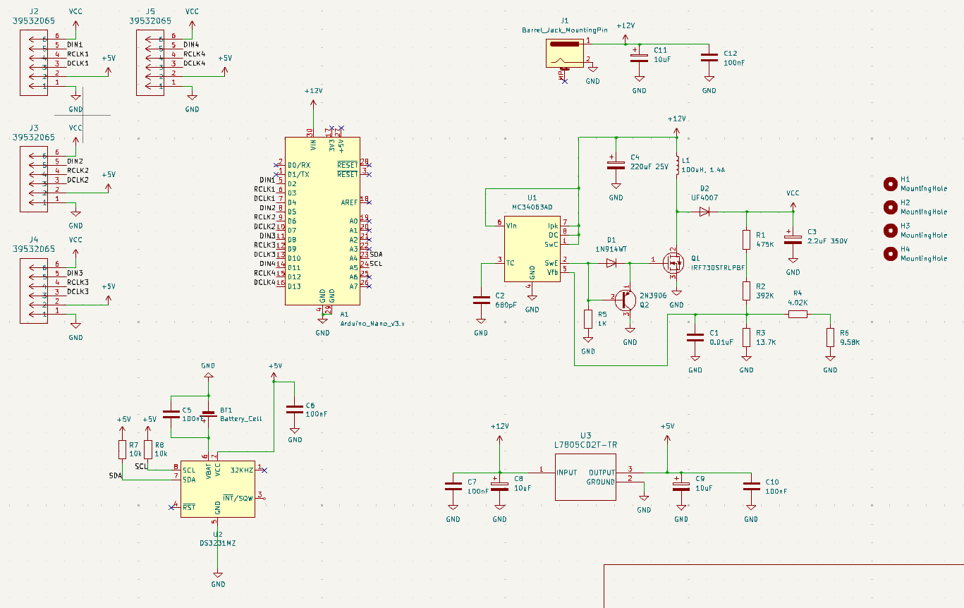
In very short words, I'm using my arduino to make a clock circuit. The arduino for the most part, is controlling the 'digits' using a TPIC6B595 shift register. There is also an RTC module that is connected to the arduino.
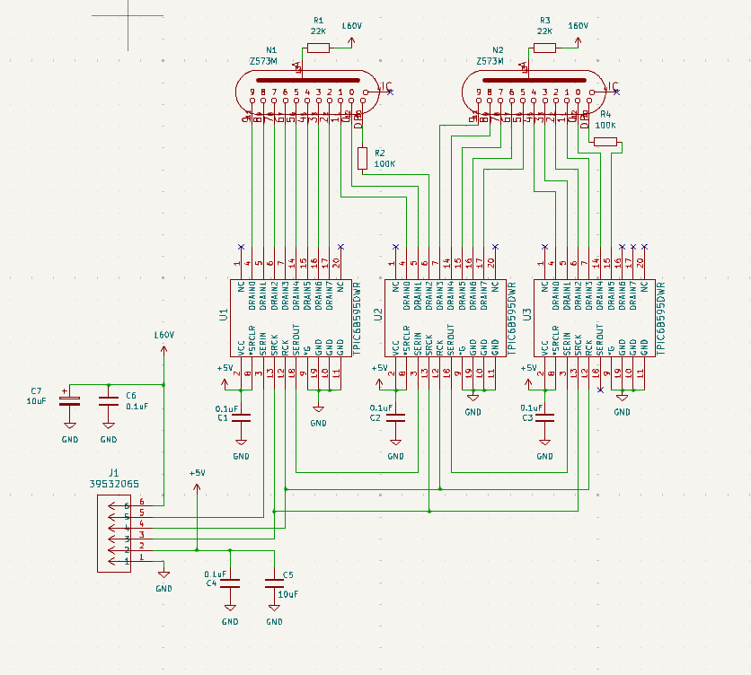
The four 6-pin jumpers on the main circuit diagram (J2 - J5) connect to one PCB board containing the two tubes and 3 shift registers each. And there are 4 such identical PCBs
So basically, J2 goes to one PCB, J3 connects to another PCB and so on.
Cool
I also make clocks and use a similar approach - several identical PCBs to control individual segments of numbers via shift registers. Only as indicators I use a flip-flop dot modules rather than high-voltage tubes.
According to the TPIC6B595 datasheet , the minimum level of the high-level input signal corresponds to 0.85 of the supply voltage. So these registers need level converters for use with 3v3 logic.
Ah nice! Yeah it was more economic to make smaller separete PCBs since PCB manufacturers usually have a minimum number of PCB copies even if you only need 1 board. So this felt way cheaper.
Yeah, the high level logic voltage is 0.85 VCC for the shift register, and it made me wonder if I can use a 3.3v VCC for the shift registers and solve the issue that way. But of course, they DID mention the 4.2 V minimum supply voltage as well, so I'm just assuming the chip itself doesnt function at 3.3V. Because one thought I had was, yeah, I could just run +3.3V on the +5V signal mentioned in the PCB by using another linear regulator with the same footprint. (In the schematic that I attached, I'm using one that converts +12 to +5 as can be seen)
The only two devices that are using the +5V supply are the shift registers and the DS3231 RTC chip. And for this thing, 3.3V is actually ideal. But for the TPIC, I'm not entirely sure.
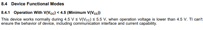
I do see this in the datasheet for the shift register, so it makes me think that using 3.3V supply for this thing might actually be ok. But they also say there's no guarantees, so perhaps I could take the risk and just pray that it sorts itself out
Alternatively, you can lower the shift register supply voltage to about 4.2-4.3v by adding a diode in series to the register supply circuit. In this case, the level of the acceptable input logic signal will also decrease and will be closer to 3.3v.
However, doing all these tricks, you enter the zone of unstable operation of the chip
It's a real shame you didn't daisy-chain/cascade those PCBs. If you had, a single level shifting board between the microcontroller board and the first shift register board would have solved the issue (and saved you 9 Arduino pins and lots of wire also, I suspect).
But now you will need 4 level shifter boards, or one board that can level shift 12 data lines.
You can use 74HCT245 as a level shifter for 8 data lines, so you would need 2x that chip.
In trying to do the reverse of getting the Nano 33 IOT to replace a mega 328, figured its best to just use logic level shifters. So wanted to ask how many lines are needing to have the shifters connected for a device that may send analog back to the Nano?