HC-SR501 PIR sensor I cant find any decent info on the two time and sensitivity adjustments and hoping someone here can quickly put me right before I revise code.
Until I got ready to mount and was doing the final testing its now false triggering.
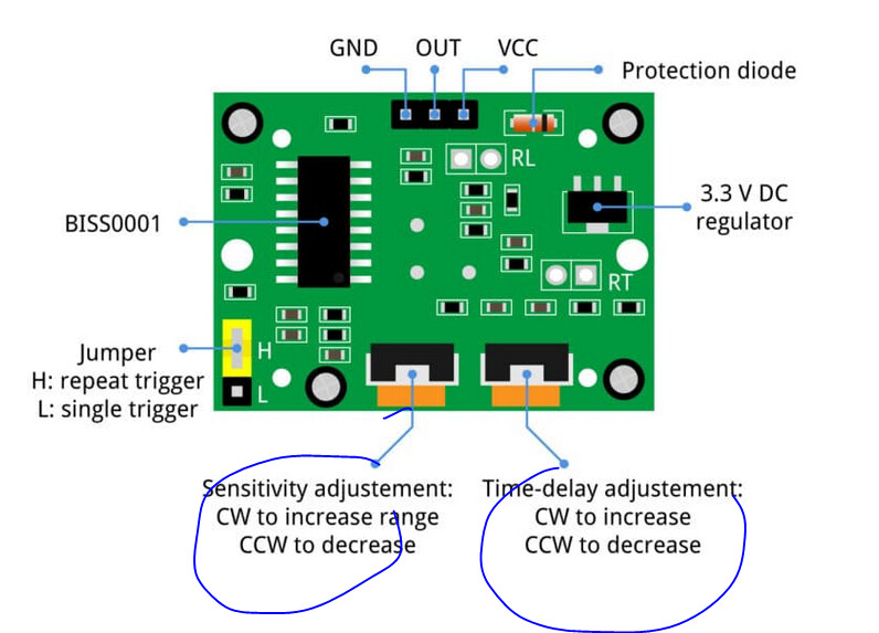
Q. with the PIR lens facing down and circuit board up I have turned both pots CCW for 3 secs delay on trigger and 3m sensitivity range.
I see a lot of discussions and information on the net but seems to be different.
Note my sensor is a XC4444 PIR Sensor but the documentation mentions
The HC-SR501 PIR sensor has a lens which focuses the IR radiation given off by living things, and toggles the output pin high when it detects movement.
I once made a game for the Raspberry Pi computer that used two of these sensors. The idea was in a kids party two kids could dance and when the music stopped they should freeze. This project detected the last one to move. Of course the delays in sensing were too long so I had to modify the board in the PIR sensors to be much smaller than you could get with the pots.
You might be interested in this and the hardware is applicable to an Arduino. I didn't suffer from false triggering so maybe there are some hints you can pick up from this.
This magazine is available as a free download See the link from @ledsyn :-
Powering the PIR with 5V creates a borderline situation. The PIR specs mention 4.5V-20V as acceptable input power. But…
The VCC pin of the PIR module feeds a 7133-1 voltage regulator through a diode. This regulator can work with an input voltage up to 24V, its nominal output is 3.3V.
The actual voltage getting to the regulator after the diode would then be about 4.3V, depending on the diode type. The specs for this regulator call for an input feed of 5.5V. A lower voltage does not guarantee an output of 3.3V, maybe not even 3V.
The PIR is based on a BISS001, which works with 3V-5V according to the specs. If the regulator delivers less than 3V the BISS001 can fail.
I have a night light based on a PIR powered by a 9V rechargeable battery. When the battery has low voltage the PIR starts with false triggering. That is my cue to install a fresh battery.
Bottom line, make sure your PIR is powered with at least 5.5V. You can get away with 5V if you are lucky. Do some testing.
A friend power his HC-SR501 all the way down to 4.5 V and it works (I haven't heard otherwise). If there are different manufacturers I'm sure there are variations in the design and components used.
What board are you using? If, for example, you use a classic Nano powered via USB, the voltage is only about 4.7 volts because there is a Schottky diode in the power path.
I've had good success with the AM312 PIR modules. These are non-adjustable and, when triggered, stay high for 4 seconds. This means you have to handle any extended on time in software. These have a push-pull output and have a 20k resistor in the output path so you must not use the Arduino pin's internal pull-up resistor.
I've had bad experience with the SR-505 modules (also non-adjustable) where electrical activity in the circuit, say a timer switching power to something, could cause a false trigger.