If anyone is willing to, please review this circuit diagram.
Thank You.

It is beautiful but a conventional schematic would be more useful. See this as an example: forum_doc/ESP32_CAM_V1.6.pdf at master · SeeedDocument/forum_doc · GitHub
Hi, @axlnneac
Welcome to the forum.
Can we please have a circuit diagram?
An image of a hand drawn schematic will be fine, include ALL power supplies, component names and pin labels.
Thanks.. Tom.. ![]()
![]()
![]()
![]()
In a word, no.
You need to approach these kinds of questions with a degree of skill and professionalism.
Crayons are not the solution. Ask Trumo.
Contact nearest rats nest spider.....
Your having a joke surely ?
But then, first time poster, a picture that appears to be a random collection of wires, with colours changing several times along the length of a so called connection, together with randomly changing angles too.
I doubt a human could draw a so called schematic so badly.
ChatGPT
Are you kidding us?


@axlnneac - Is this a fire truck based on object avoidance (but fire seeking)? Here's your drawing!
--------
+-------------------+ |MOTOR |
| --------- | |DRIVER|
| |ESP32CM| | |HG7881| -------
| +-------|+5V 3V3| | | OUT1+|---|LEFT |
| | +-----|GND 16|-+ | OUT1-|---|WHEEL|
| | | | 00| +--------|A-1A | -------
| | | |12 | | +------|A-1B | -------
| | | |13 GND| | | | OUT2+|---|RIGHT|
| | | +-|15 VCC| | | | OUT2-|---|WHEEL|
| | | +-|-|14 | | | +----|IN+ | ------
| | | | | | 03|--+ | | +--|IN- | ------
| | | | | |02 01|----+ | | | OUT3+|---|5VDC|
| | | | | |04 GND| | | | OUT3-|---|PUMP|
| | | | | --------- | | -------- ------
| | | | | | |
| | | | | | |
| | | | +----------------|-|-----------------------+
| | | +------------------|-|---------------------+ |
| | +--------------------|-+---------+ | |
| +-|--------------------+---------+ | | |
| | | -------- -------- | | ------- | |
| | | |POWER | | BUCK | +-|---|SERVO|-+ |
| | | |SUPPLY| |CONVRT| | +---| 0 | |
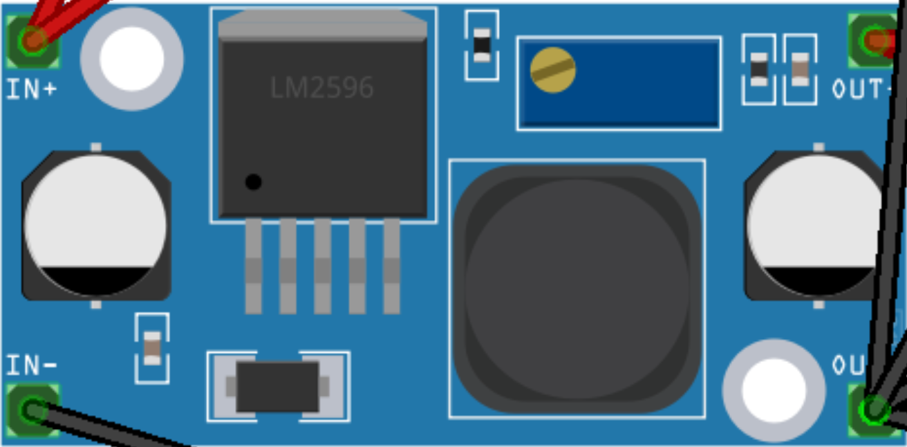
| | | |7.4vdc|---->| 5VDC |----+ | ------- |
| | | | GND |---->| GND |----|-+ |
| | | ------- -------- | | ------- |
| | | -------- | +---|SERVO|---+
| | | | FIRE | +-----| 1 |
| | | |SENSOR| -------
| +-|------------------|GND |
| +------------------|VCC |
+----------------------|SIGNAL|
--------
I am not convinced this scheme is equivalent to the scheme in post#1. But despite the lack of fancy colors it is way easier to follow. ![]()
Improvement would be to have gnd at bottom, vcc at top and power supplies in upper left corner.
That would also reduce crossings.
Yes, wire for wire I am sure it is not exact.
Modular:
ESP32 cam is powered by 7.4VDC through a Buck converter, controlling a DC motor driver for two wheels (steered by servis) and a pump (for water?) while taking input from an IRrx (my guess, looking for fire). It is more accurate than spaghetti bolognese. : )
I do my art in notepad/gedit, but ASCIIFlow and Textik are ASCII schematic generators in graphic form. Looking for an ASCII to graphic that works.... OP could then upload and use.
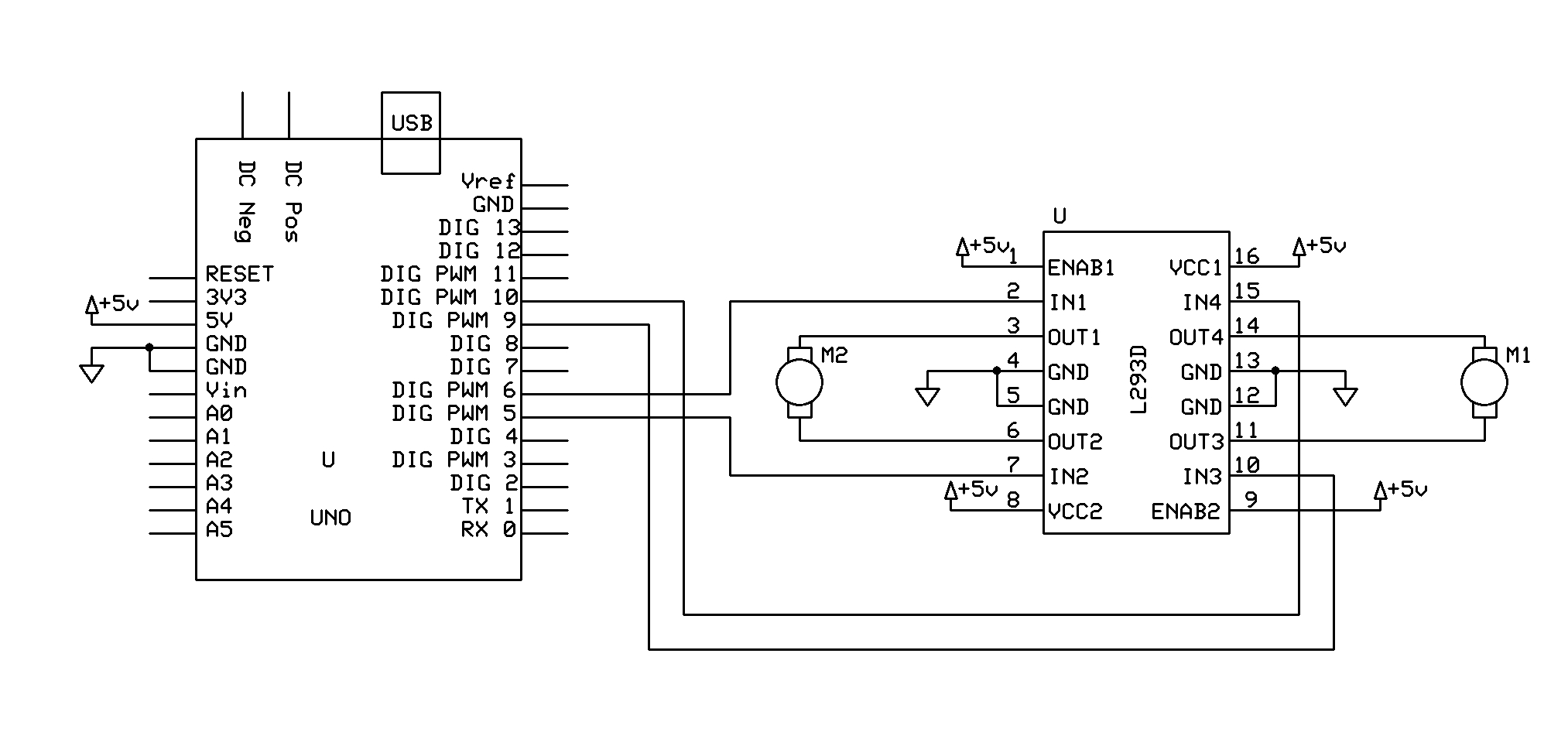

The Express schematic CAD allows you to make what ever component you like or edit existing components and symbols.
The web site has extra components and symbols from other users to use as well.
It doesn't have all the parameters of Altium or Eagle for each component, thank goodness.
I like it because it takes no time to boot, has a clean desktop, is just BLACK and WHITE and easily produces a BMP image that can be cut, pasted, converted and abused in any way.
KISS for quick simple schematics.
Tom.. ![]()
![]()
![]()
![]()
The servos are for PAN/TILT for the ESP32 CAM.
Thanks for the drawing but it works on the concept of using a TinyML model to detect if there is a fire and then re-checking it using the Flame sensor to finally extinguish the fire.
I'll try that! Thanks.
Sure, I'll try to make one
Oh, cool. What are the (small) DC motors moving?