Trying to make a pump moving water from one container with a simple push button to another to begin with.
Works flawless when I power the arduino via USB and computer but not via USB adapter to wall socket. The USB adapter I use is an iPhone 5V 1A. Problem is when i connect to wall socket, the pump turns on immediately on low RPM (?) without pressing the button. When connected via usb to computer, it does not ramp up before i press button and stops when i release it.
Please let me know if anything is missing. My thought is that there is some grounding issues when connected to wall socket so the power goes straight to pump but i dont really know.
They are called that because that is one of the few applications they are suited for. They are not suited to any applications involving motors, pumps, relays, solenoids etc because they cannot provide very much current and have a low capacity.
I can't see how the battery (which as others have pointed out is not suitable for driving a motor), is connected to the motor. The ground is a direct connection... but what path does the +9v take to get to the motor? Can't see any connection through the transistor.
A schematic would be much easier to see what is connected to what.
Can you post an English data sheet please? English is the correct language for this section of the forum, so that data sheet is not very useful. Even the English text in it is blurry and difficult to read.
You need a 560 ~ 1k Ohm resistor between pin 9 and TIP120 base. You are going to put about 8.5 Volts on a 3 Volt motor? You need a 10k anti float resistor from pin 2 to GND.
You do not need the pull-down resistor for the button. Simply connect the button between the Arduino pin and ground and use INPUT_PULLUP.
The tip120 is a Darlington transistor and will have a high voltage drop. A base resistor is needed, otherwise the current drawn from the Arduino pin could damage the Arduino. A logic level MOSFET would be a better choice.
I also cannot see how the motor can run if the diagram you posted is accurate. It is good that you have a flyback diode, but the motor should be connected in parallel with the diode and it is not.
That is still a mystery... I would really like to see a schematic, or even a photo of your setup. The Frizty diagram you posted just does not support the behaviour you describe.
No, as mentioned, the 9V battery is unsuitable. Also the flyback diode does not seem to be correctly connected, but it is a little hard to tell because the wiring is like spaghetti. Position the components on the schematic so that the length of the wires is minimised and crossed wires are minimised.
Re-read the earlier answers you got about where resistors are and are not needed.
Not much. As sometimes happens, an important figure is missing, which is the stall current. Use a multimeter to measure the motor coil resistance. You can work out the stall current from that.
Can you provide a link to the project book? I don't understand the purpose of the diode in the diagram... it's seems to be block anything getting to the motor. Normally diodes are inserted backwards in parallel across the motor to protect against reverse voltage spikes.
Can you show a picture of both powering via USB to the computer, and via USB to the power jack.
After rewiring it all, I could finally find that there was a failed jumper wire or connection from the resistor that comes after the button to ground, now it all works as planned.
For you asking, it is based on the MOTORIZED
PINWHEEL task in the Arduino UNO projects book (dont know if i can post a link here?). Just switched the motor to a pump.
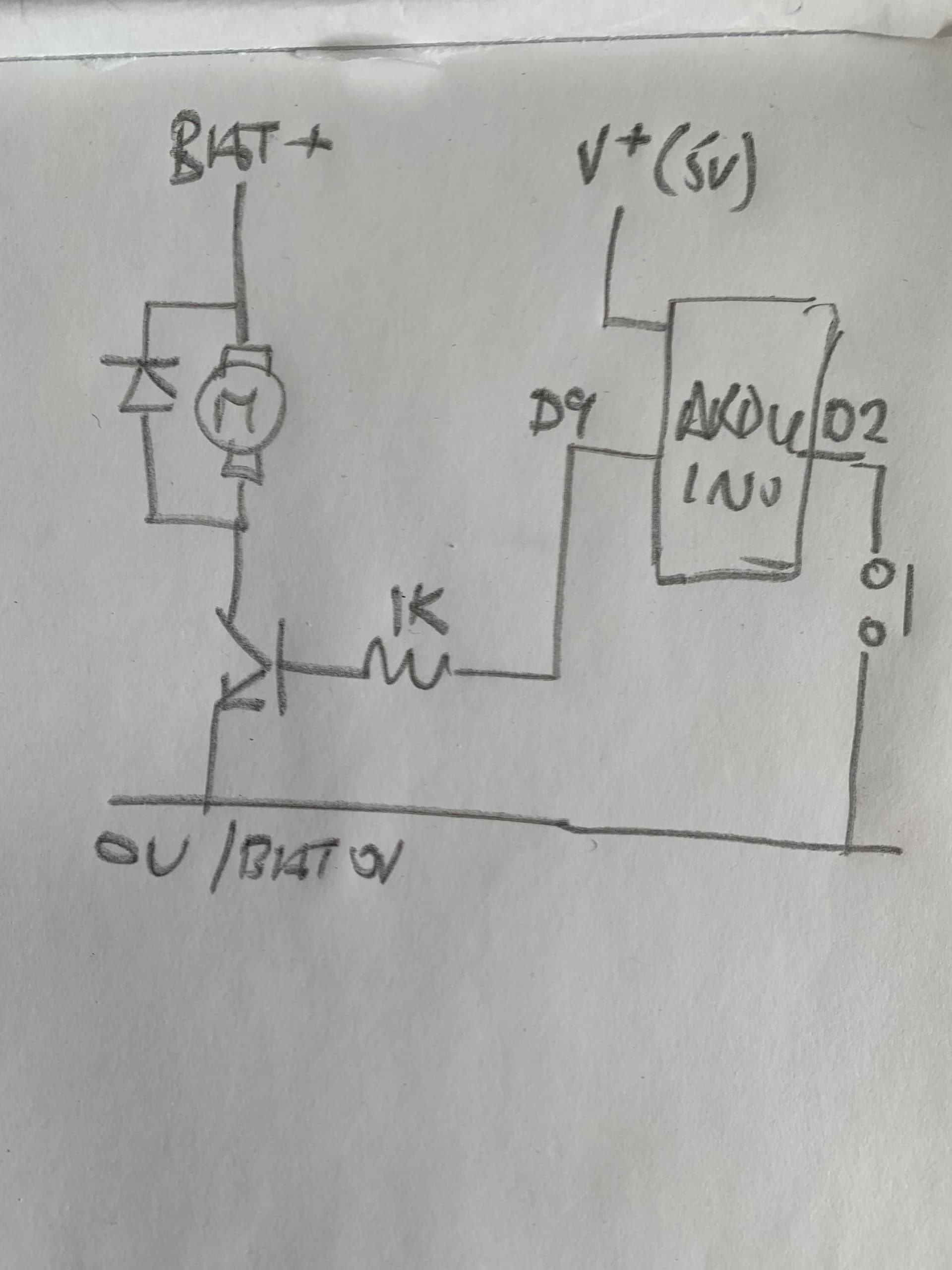
This is the sort of hand drawn “quick” schematic people ( hopefully ) want ; note +ve supply at the top , Ov at the bottom . It’s simple to read and understand . Put a blob on wire junctions , I like to put a jump over crossing wires .
“INPUT_PULLUP” used on the switch line .
I think this is how your circuit should look .
Please don’t waste your time with that 9v battery
You will see some schematics with positive supply on the left and 0v on the right , that’s ok too, some with signal flow from left to right and power supply top and bottom . A long as it’s logical that’s fine .( did mine with signal flow right to left ( I’m left handed lol )).
You can do good schematics with Fritzing , using schematic NOT Breadboard


