Hello! I'm electronic and electrical enthusiast. I want to try to make a project about measuring the mains current and power factor of our house. So, I've searched existing project related to power factor and current measurement and I found these two:
Please do not duplicate your questions as doing so wastes the time and effort of the volunteers trying to help you as they are then answering the same thing in different places.
Please create one topic only for your question and choose the forum category carefully. If you have multiple questions about the same project then please ask your questions in the one topic as the answers to one question provide useful context for the others, and also you won’t have to keep explaining your project repeatedly.
Repeated duplicate posting could result in a temporary or permanent ban from the forum.
Could you take a few moments to Learn How To Use The Forum
It will help you get the best out of the forum in the future.
Well done for posting a proper, clear, well drawn schematic.
I don't know if it will work but I have some concerns.
First, please describe how you think it works.
You power U2 with 9V and connect the output to a 7486 powered with 5V, so whenever the output of U2 goes above 5V it is trying to feed over 5V into a device powered at 5V. At best this is bad practice, at worst something will get fried.
I've not done much with circuits like this but from my limited experience the high pass filter formed by C3 and associated resistors will mean you feed more of the junk from the mains into the subsequent circuits than the actual mains current you want to measure.
The circuit will do nothing without code, so, where is your code?
What are you expecting on the inputs to the Arduino and how do you propose to interpret them as voltage, current and phase?
All the above are just initial thoughts, this is not something I've tried. I will be very interested in what others says.
I don't know if this will work either but U5 and U6 should be addressed. U5 and U6 are dual op amps. You can use U5b to do what U6a is doing and eliminate U6. Or terminate U5b and U6b.
OK, so I congratulated you on posting a nice, clear schematic
Shame about the code as @UKHeliBob has pointed out
If I were doing this I'd build the thing and use an oscilloscope to see if it does what I expect. I think you'll find it doesn't, but, well, that's how you learn.
When it comes to calculating components for filters I don't have much of a clue. As it is a high pass filter, what is its cut of frequency? I would think it needs to be below maybe 25Hz. Slightly off topic but also slightly relevant I did once try something similar to use as an AC voltage drop from mains (don't do this unless you know what you are doing!). The AC I got out was a mess because what I was doing was filtering out most of the 50Hz but letting through the higher frequencies that are also in the mains and make it such a mess. I then realised that I'd derived from my RC circuit that sine and cosine are each others integral, before realising that's what I was taught at school.
I hope that something in that rambling helps in some way.
One thing to bear in mind , that in a average household power factor is pretty well always 1.0.
If you just want to measure power ( rather than making as a project ) the easiest and safest method ( and the cheapest ) is to buy an electricity meter or take an output from your existing meter
Probably, but look at the polarity marks on the 220/12 volt transformer. They are using the windings out of phase to the mains power. Correct phase is when the dots are on the same end of the drawing. So, if you try to duplicate this, you need to use a transformer that shows the correct phasing on the case of the transformer. Did you get a bill of material with the schematic?
1. Detect positive (or negative) zero crossing points for both voltage and current waves.
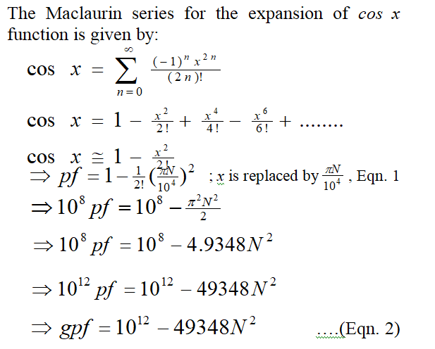
2. Use "interrupt pins" to measure the time (which is proportional to power factor) between these two zero crossing points. Say, it is N us. or
Use set-reset flip-flop to derive a single pulse from the zero crossing points of the waves of Section-1. The duration of the "single pulse" is proportional to power factor. (The duration of the single pulse can be measured using pulseIn() function or "timer capture mode".)