Hey guys,
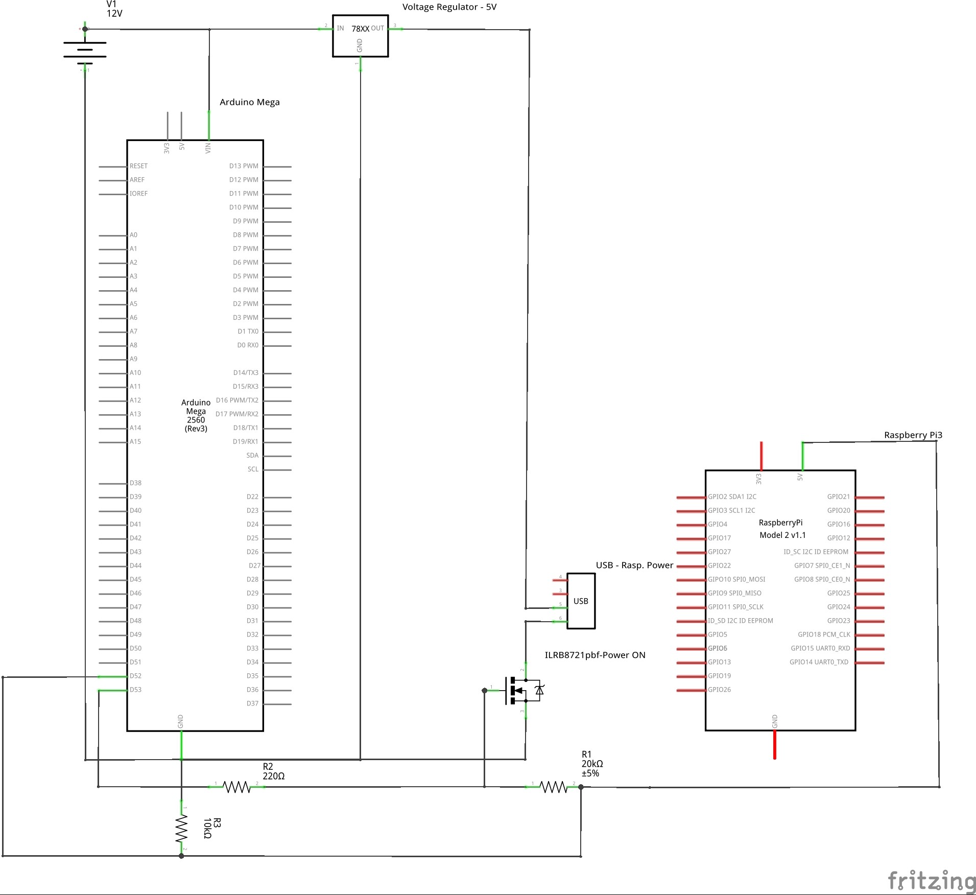
as a part of my project I need to control the power on and shutdown of a raspberry pi 3 with a momentary button, using an arduino mega. My idea is to use the circuit in the picture.
The main power come from a pico psu (12 V) and it is converted to 5V by a step down voltage regulator, not exactly the one in the schematics, but one of this.
The power on circuit is controlled by a IRLB8721pbf mosfet with the gate connected to the arduino pin 53 and to a pull-up resistor (R1) connected to the +5V GPIO PIN of the raspberry pi that will prevent the shutdown of the raspberry when arduino is resetting or when flashing a new sketch (floating PIN).
The 5V PIN of the raspberry is also connected to the arduino PIN 52, in order to check the state of the raspi.
About this part of the circuit I have 2 doubts:
Is the voltage drop caused by IRLB8721pbf small enough for the Raspberry pi (Rds On =8.7 mOhm@10V)? Datasheet here
Is safe to connect directly the +5V GPIO Pin of the raspberry pi to the arduino PIN 52 (configured as input PIN)?
The second part of the circuit is for the shutdown and it is based on this tutorial
Basically is a python script on the raspberry that set the GPIO pin 13 as input with the internal pull up resistor turned ON and when this PIN is shorted to ground a shutdown command is executed.
As for the power on part, the circuit is controlled by a IRLB8721pbf mosfet with the gate connected to arduino pin 50 with the help of a pull-down resistor R5 in order to prevent accidental shutdown.
My doubt here is if it safe to connect all the ground (+12V line, +5V line, Arduino GND PIN, Raspberry GND PIN) to the same bus.
franz-unix:
Hey guys,
as a part of my project I need to control the power on and shutdown of a raspberry pi 3 with a momentary button, using an arduino mega. My idea is to use the circuit in the picture.
The main power come from a pico psu (12 V) and it is converted to 5V by a step down voltage regulator, not exactly the one in the schematics, but one of this.
The power on circuit is controlled by a IRLB8721pbf mosfet with the gate connected to the arduino pin 53 and to a pull-up resistor (R1) connected to the +5V GPIO PIN of the raspberry pi that will prevent the shutdown of the raspberry when arduino is resetting or when flashing a new sketch (floating PIN).
The 5V PIN of the raspberry is also connected to the arduino PIN 52, in order to check the state of the raspi.
About this part of the circuit I have 2 doubts:
Is the voltage drop caused by IRLB8721pbf small enough for the Raspberry pi (Rds On =8.7 mOhm@10V)? Datasheet here
Is safe to connect directly the +5V GPIO Pin of the raspberry pi to the arduino PIN 52 (configured as input PIN)?
The second part of the circuit is for the shutdown and it is based on this tutorial
Basically is a python script on the raspberry that set the GPIO pin 13 as input with the internal pull up resistor turned ON and when this PIN is shorted to ground a shutdown command is executed.
As for the power on part, the circuit is controlled by a IRLB8721pbf mosfet with the gate connected to arduino pin 50 with the help of a pull-down resistor R5 in order to prevent accidental shutdown.
My doubt here is if it safe to connect all the ground (+12V line, +5V line, Arduino GND PIN, Raspberry GND PIN) to the same bus.
I think most people will find that diagram very difficult to read, it made me feel dizzy.
Do you have a schematic, that woould be much easier to read ?
Why use a 5V regulator when you already have the picoPSU?
Why did you pick that particular MOSFET?
Why use an Arduino for something as simple as a latch?
Check the peak current draw of the RPi, use Ohm's law to calculate the voltage drop over RDS.
Obviously not. The RPi's IO are only rated for 3.3V, 5V will destroy it.
I don't think you want to disconnect the ground on the Pi with a MOSFET, I think it is better to stop the power from going into the 12V to 5V converter.
I can show what I did to power off a Pi Zero.
First look at my RPUno board which has a P-Channel MOSFET (PMOS) that I can turn off the power to the VIN pin for the shield.
Next check out the RPUpi shield which the Pi Zero plugs into. The shield has a converter that turns the VIN power to 5V for the Pi Zero. The shield also has a microcontroller that does a few things, one of its pins (PB0) is set as a weak pull-up which a switch can pull down (e.g. an on-site halt). The BCM6 pin of the Pi Zero is connected to that weak pull-up and monitored with a shutdown script.
In the setup, the shield microcontroller can Halt/Shutdown the Pi Zero by pulling down the SHUTDOWN (e.g. on a timer). It can also be accessed by the RPUno board through I2C to halt the Pi Zero. The RPUno can also be used to track how much input current is used by the Pi Zero to tell when it is safe to turn off power (e.g. the Pi's SD card does some things that may show up in the power usage even after it has halt).
A Pi3 takes more power than the converter I used but perhaps the setup could give you some ideas.
As a suitable P-MOS I have found this FQP27P06 that seems to be adequate (RDS(on) = 0.07Ω @VGS = -10 V and VGS Th = -4.0V), but is there something better?
Because I don't have yet the components to to test the circuit directly, I have tried a simulation (very ugly drawn, but works ), visible here (close one of the two +5V switches to see what happens when powered on).
All seems to works fine, and, after some trials, I have found that increasing the value of R1 to 1MOhm reduces the amount of power wasted through the N-MOS branch of the circuit... But is this resistance value to high and, as a consequence, sensitive to some noise?
P.S.: The scope of R6 is to keep the gate of the N-MOS closed when the Raspi is off and the Arduino is booting
I'm guessing this is going to be used in an automobile application?
If so, why not get the arduino and pi both on the 5V side and use a logic level p-ch mosfet for the pi-power instead of throwing 12v (and higher) on the I/O pins of both?
Hi, I don't use an LM7805, it is in the schematics only because is the most similar things that I have found in fritzing.
In the real circuit I will use one of this (waiting for delivery).
In the last days I have also found this switching voltage regulators that seems ok
@tinman13kup no it is not a part of an automibile application.
I have only a +12V line in coming from a very common power supply like this, that will supply both arduino and the raspi
The scope of R5 is to keep the gate open when the arduino is booting or resetting. I need this feature because on the raspi I have installed avrdude (to compile and upload sketches) and I don't wont that the raspi shutdown when arduino is resetting. It is not reported in the schematisc but the raspi and the arduino are also connected via usb and exchange data via serial port.
The scope of D25 is to check the status (on / off) of the raspi and display it through a RGB led associated to the momentary switch (a capacitive switch will be very cool!) that triggers the power on / shutdown of the raspi.
However I'm not sure that this will work with the +5V gpio pin because, according to this post , this pin is always powered also when the raspi is in shutdown. Probabily for this purpose I need to use the UART TX pin (+3.3V)
Sorry I'm very noob in electronics, but what is the function of a capacitor across the output (micro usb)?
franz-unix:
Sorry I'm very noob in electronics, but what is the function of a capacitor across the output (micro usb)?
Because of the fact that this is a digital circuit and among other things your power supplies are switch mode, there is the possibility of switching noise occurring on the 5V rail, this can cause glitches in the execution of your code and any voltage sensitive devices.
The 0.1uF capacitor placed at suitable places in a circuit, the caps filter the noise out.
Tom...