Pro Micro clone programmer error

I am pretty new to Arduino and I have a Pro Micro board with a USB-C connector. I don't remember where I got it from - it's a clone I think. I chose Arduino Micro from the board manager. The board connects OK and three red LEDs turn on. When I upload a blank (basic) sketch, I get the following error messages:

Connecting to programmer: .
Found programmer: Id = "CATERIN"; type = S
Software Version = 1.0; No Hardware Version given.
Programmer supports auto addr increment.
Programmer supports buffered memory access with buffersize=128 bytes.

Programmer supports the following devices:
Device code: 0x44

I assume there is some additional initialization procedure to get this board to work. Can someone help me with that? Thanks.

The question is, did your code get uploaded?

It is just a blank sketch. It compiles, says Uploading, the error messages appear, and then it says Done uploading.

That's not an error message, its just an info.
Under file->preferences select 'Show verbose output during ... upload to see all messages.

It would be better to select a basic example -> the blink sketch. So you cann see if it works.

[Edit] - Sorry the last may not be a good idea. As far as I remember many - if not all - pro micro don't have an on board LED the blink sketch addresses.

HI, @kentm

Where does it say its an error?

Write a simple code that counts up and outputs to the serial port to see if your code is running.

If you use blank code, how do you know its loaded?

What OS and IDE version are you using?

Can you please post an image of you pro micro?

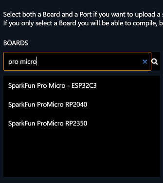
From IDE 2.3.5 boards are;

Thanks.. Tom.... :smiley: :+1: :coffee: :australia:

So upload something that you can verify. I expect that it works (if your selected board matches your device).

ps. you have one of the nicest user icon I have seen around here

A Pro Micro does not have the built-in LED. So that will not help :rofl:

You can use the Rx and Tx LED however; see https://learn.sparkfun.com/tutorials/pro-micro--fio-v3-hookup-guide/all#example-1-blinkies.

@TomGeorge: Thanks for helping. To answer your questions:

I assumed it is an error message because it appears in red, when other info is white.
I used blank code just to see if it connects (correct port, etc.) . This has worked in the past on other boards just as a quick check, and I haven't seen this red message about programmer before.
I have Windows 11, Arduino IDE 2.3.6

I found the SparkFun ProMicro board in the boards manager, selected it, and connected my board. In the interest of changing only one thing at a time, I again attempted to upload a blank sketch. This time, I got a different red (error) message saying:

avrdude: ser_open(): can't open device "\.\COM11": The system cannot find the file specified.
Failed uploading: uploading error: exit status 1

At the very bottom of the sketch window it says SparkFun Pro Micro on COM11 (not connected). Also, now I get a Windows notification: USB device not recognized. It seems the connection through the port is not working at all now.

So, I think I need to get the board recognized and be able to load a blank sketch with no error messages before I proceed to actual code that does something.

@kmin Yes, my icon is lovely like yours. Yours actually has my initials, whereas mine is the first two letters of my first name.

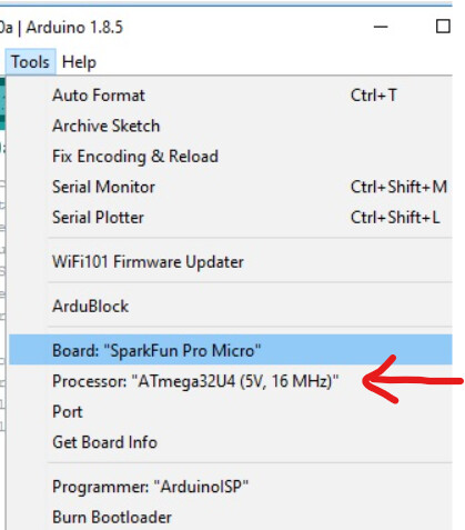
Is it showing processor: ATmega32U4 16MHz?

Where would I find that?

I think Arduino Micro should work as well.

I think that the default setting is 3.3V / 8MHz. If you program a 8MHz Pro Micro as a 16 MHz or vice versa you can use the following approach to get it right.

  1. Select the correct clock frequency; it seemed to have worked when you selected the Arduino Micro so it's probably 16 MHz.
  2. Upload an innocent sketch (blank or one of the blinkies (see my earlier reply).
  3. When the IDE reports the memory usage, double tap the reset button. Upload should now succeed.

I know that a Pro Micro does not have a reset button; either connect one between GND and reset pin or use a piece of wire between GND and reset pin.

Thanks, all, for your expert help. I chose the 16 MHz option, performed the double tap, and it works! My LED is blinking merrily.
Editorial note: I think it's amazing, and super cool, that people like you help newbies like me. I hope to someday pay it forward and help others as well. Question: How are you set up to see and respond so quickly? Are you monitoring various categories constantly, or do you just get onto the forum once in a while and jump in?

Nice! There is a never ending stream of thousands of people requesting assistance and only some dozens of helpers here to try to provide it

There are a lot of opportunities to contribute to the forum and the Arduino initiative in general. Although some of the requests we get here require a deep understanding of the relevant subject matters in order to provide effective assistance, others are on quite basic subjects that we learn well by the time we reach an intermediate level of experience with Arduino. As most people, I first visited Arduino Forum purely as a resource for my own projects. I found the technical discussions I saw here to be quite interesting and so started to follow them for the sake of general advancement of my knowledge. I soon started to notice questions where I thought "hey, I know the answer to that!", and so was drawn in to contributing.

I "watch" each of the specific forum categories that are related to subjects in which I am interested/knowledgeable. The forum then sends me notifications whenever someone creates a new topic in one of the categories I am "watching".

If you visit the individual category pages that are listed on the left hand column of the page here:

https://forum.arduino.cc/categories

you will see a 🕭 button near the top right. If you click that button, a menu will open which will allow you to set your forum account to "watch" that category. I use the "Watching First Post" setting because I only want to receive a single notification for each new topic in the category, rather a notification for every one of the thousands of replies in every topic in the category.

Note that we have a nested category structure, so there are subcategories inside the top level categories (e.g., Other Hardware > 3rd Party Boards).

I review each of the individual new topics that I am notified of. If the topic is of interest, I click the 🕭 button that is on the right side and bottom of the topic, and select "Watching" from the menu that opens. I will then also receive a notification for each of the replies in that topic, allowing me to follow the discussion as it progresses. I have my forum account preferences configured to automatically "watch" any topic in which I make a reply, so I only need to explicitly configure a topic as "watching" in cases where I have not yet participated.

You can configure how the forum provides notifications in your "Emails", "Notifications", and "Tracking" account preferences:

1 Like

Just to make it clear, after it started working on 16 MHz you do not need the double tap reset trick anymore.

It's a pleasure. The forum is, in my view, all about sharing knowledge. So if I see something that I'm knowledgeable about I try to help.

Usually I have the forum open permanently on my PC and when I'm stuck with something that I'm doing I quickly look at the forum to see if there are new topics so I can reset my brain. You were lucky that I did see this one early and that I had the knowledge :wink:

Some tips to prevent issues.

===

If you intend to use the board as a HID, build in a failsafe. It's very easy to get the board in a state where

  1. it spams the PC with data.
  2. keys presses get stuck in the PC.

As a result you can have a hard time to e.g. upload a new sketch.

The failsafe will be a pin that you can connect to GND. If that pin is HIGH it will prevent the board from spamming the PC. In the below example I use A0 as the failsafe pin.

const uint8_t safetyPin = A0;

void setup()
{
  pinMode(safetyPin, INPUT_PULLUP);
  
  while(digitalRead(safetyPin) == HIGH)
  {
    // do nothing
  }
}

void loop()
{
  // your HID functionality here
}

This code will get stuck in setup() till you ground the safety pin; that way you can prevent the spamming.

This will not prevent a key (e.g. <CTRL>) getting stuck in the PC; as a result when you press a on the normal keyboard it will become <CTRL>A and usually it will e.g. select all code in the IDE. Therefore you must make sure that you always release keys. The basics for the loop() function to achieve that is below.

void loop()
{
  if(digitalRead(safetyPin) == HIGH)
  {
    keyboard.releaseAll();
    return;
  }

  // your HID functionality here
}

If the safetyPin is not connected to GND the loop() will release all keys and prevent further HID functionality.

===

You will often see code like below when using the Serial interface.

void setup()
{
  Serial.begin(115200);
  while(!Serial) {}
}

This is used if you want to make sure that you will not miss the first data that is send to e.g. serial monitor. The code will wait till the a communication channel with the PC is opened (e.g. opening the serial monitor).

This however has the disadvantage in stand-alone use of the board as it will simply hang on the while(!Serial) {}. You can either remove the while(!Serial) {} line or use a workaround can be to add a timeout as shown below

void setup()
{
  Serial.begin(115200);
  while(!Serial)
  {
    if (millis() > 3000)
    {
      break;
    }
  }
}

This will wait for the communication channel to be opened or till 3 seconds (3000 milliseconds) have passed.

===

When using the board with external power on the RAW / Vin pin and using USB to print data over the Serial interface you can bring your board to a near grinding halt. The scenario is that your board is connected to external power (e.g 9V) and you're happily debugging using serial monitor; now you disconnect the USB (and keep the external power connected; the result is that the processor can no longer get id of the data and your board will eventually come to a near grinding halt.
To prevent that you can check if there is still space in the underlaying software Serial buffer; you need to do this for every print/println/write

void loop()
{
  if(Serial.availableForWrite() > X)
  {
    Serial.print(something);
  }
}

where X is basically the number of bytes that you want to send. If you want to play it safe you can use e.g. 60.

Note:
Codes not tested as I'm currently using my boards for something else.
1 Like

Post#18 should be on a good practice manual. Thanks for sharing.

Turns out I am still having issues connecting to the Pro Micro. If I attempt to upload a sketch without doing the reset double tap, I get this (if there is a better way than a screenshot, let me know) and the code doesn't run (no blinking):
without reset.pdf (224.7 KB)

If I upload the sketch with the reset double tap, I get the following, as well as a pop-up Windows message that disappeared before I took the screenshot (something about the com port not working). The sketch works (led blinks), BUT the serial monitor doesn't work.
with reset.pdf (220.3 KB)

Here is my code:

//A simple sketch to check if a board is working.

//connect a jumper from pin 5 to a 1k resistor.
//connect the resistor to an LED, and the LED to gnd.
//connect arduino board to gnd.

//if the board doesn't connect automatically, hit reset
//(connect reset to gnd) twice after the memory usage info shows.

int LED_pin = 5;

void setup() {
pinMode(LED_pin, OUTPUT);
Serial.begin(9600);
delay(2000);
Serial.println("Initialize Serial Monitor");
}

void loop() {
digitalWrite(LED_pin,HIGH);
delay(1000);
digitalWrite(LED_pin,LOW);
delay(1000);
}

Really struggling to use this Pro Micro; haven't had these issues with 3 other types of arduinos. Any suggestions appreciated.