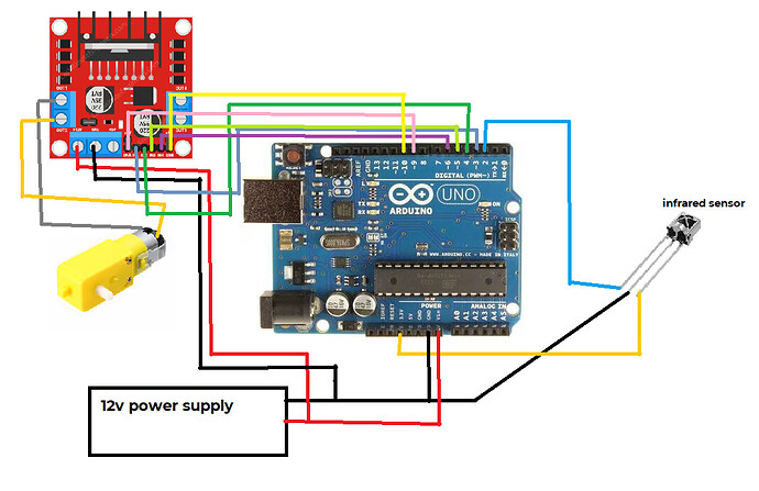
so my motor will only spin when i write 255 in analog to the enable pins, it will not spin using values from 0-254
i tested it with this code, the motor indeed only spins when the value is 255
also sorry for writing the code in indonesian, its for a competition
You need to post ALL your code.
It could be a pin that is incapable of producing a PWM signal.
What sort of Arduino are you using?
#include <Servo.h>
#include <IRremote.h>

const int recv_pin = 2;
const int motor1pin1 = 3;
const int motor1pin2 = 4;
const int motor1pinENA = 9;
const int motor2pin1 = 5;
const int motor2pin2 = 6;
const int motor2pinENA = 10;
const int pinServo = 11;

Servo tangan;

void setup() {
  IrReceiver.begin(recv_pin);
  Serial.begin(9600);
  tangan.attach(pinServo);

  pinMode(pinServo, OUTPUT);
  pinMode(recv_pin, INPUT);
  pinMode(motor1pin1, OUTPUT);
  pinMode(motor1pin2, OUTPUT);
  pinMode(motor1pinENA, OUTPUT);
  pinMode(motor2pin1, OUTPUT);
  pinMode(motor2pin2, OUTPUT);
  pinMode(motor2pinENA, OUTPUT);

  tangan.write(155);
}

void loop() {
  // put your main code here, to run repeatedly:
  if(IrReceiver.decode())
  {
    Serial.println(IrReceiver.decodedIRData.decodedRawData , HEX);

     switch(IrReceiver.decodedIRData.decodedRawData)
     {
       case 0xFF00DB24: //maju
        maju(255);
        break;

       case 0xE619DB24: //maju pelan
        maju(254);
        break;

       case 0xFE01DB24: //mundur
        mundur(255);
        break;

       case 0xEF10DB24: //mundur pelan
        mundur(200);
        break;

       case 0xFD02DB24: // kanan
        kanan(255);
        break;

       case 0xE31CDB24: // kanan pelan
        kanan(200);
        break;

       case 0xFC03DB24: // kiri
        kiri(255);
        break;

       case 0xF20DDB24: // kiri pelan
        kiri(200);
        break;

       case 0xF40BDB24: // buka tangan
        Serial.println("buka tangan");
        tangan.write(155);
        break;

       case 0xBC43DB24: // tutup tangan
        Serial.println("tutup tangan");
        tangan.write(25);
        break;

       default:
        digitalWrite(motor1pin1, LOW);
        digitalWrite(motor1pin2, LOW);
        digitalWrite(motor2pin1, LOW);
        digitalWrite(motor2pin2, LOW);
      }

    delay(300);
    IrReceiver.resume();
  }
}

void maju(int kecepatan){
  Serial.println("maju");
     digitalWrite(motor1pin1, HIGH); //motor kanan maju
     digitalWrite(motor1pin2, LOW);
     digitalWrite(motor2pin1, HIGH); //motor kiri maju
     digitalWrite(motor2pin2, LOW);
     for(int i = 0; i <= 255; i++)
     {
       analogWrite(motor1pinENA, i);
       analogWrite(motor2pinENA, i);
       delay(20);
     }
     for(int i = 255; i >= 0; i--)
     {
       analogWrite(motor1pinENA, i);
       analogWrite(motor2pinENA, i);
       delay(20);
     }
}

void mundur(int kecepatan){
  Serial.println("mundur");
     digitalWrite(motor1pin1, LOW); //motor kanan mundur
     digitalWrite(motor1pin2, HIGH);
     analogWrite(motor1pinENA, kecepatan);
     digitalWrite(motor2pin1, LOW); //motor kiri mundur
     digitalWrite(motor2pin2, HIGH);
     analogWrite(motor2pinENA, kecepatan);
}

void kanan(int kecepatan){
  Serial.println("kanan");
     digitalWrite(motor1pin1, LOW); // motor kanan mundur
     digitalWrite(motor1pin2, HIGH);
     analogWrite(motor1pinENA, kecepatan);
     digitalWrite(motor2pin1, HIGH); //motor kiri maju
     digitalWrite(motor2pin2, LOW);
     analogWrite(motor2pinENA, kecepatan);
}

void kiri(int kecepatan){
  Serial.println("kiri");
     digitalWrite(motor1pin1, HIGH); //motor kanan maju
     digitalWrite(motor1pin2, LOW);
     analogWrite(motor1pinENA, kecepatan);
     digitalWrite(motor2pin1, LOW); //motor kiri mundur
     digitalWrite(motor2pin2, HIGH);
     analogWrite(motor2pinENA, kecepatan);
}
JCA34F
November 19, 2022, 4:43pm
5
Using the servo library disables PWM on pins 9 and 10, try using pins 3 and 11 for ena1 and ena2, use 9 or 10 for the servo(s).
1 Like
Why are there no servos in the diagram but lots of them in the code?
Why is the IR sensor connected to the 3V3 line? This means you can only get 3V3 signals out of it which is insufficient to drive a 5V input. Why is there no supply decoupling around the IR sensor like it shows in the sensor's data sheet?
And also, the IRremote library uses a timer which will prevent PWM on two other pins. By default, Servo and IRremote try to use the SAME timer (Timer1) so you will need to tell IRremote to use a different timer (Timer2). That leaves the two PWM pins (Pins 5 and 6) from Timer0 for your enable pins:
how do you tell IRremote to do that?
peiwastaken:
how?
#define IR_USE_AVR_TIMER 2
#include <IRremote.hpp>
johnwasser:
#include <IRremote.hpp>
oh i was also wondering what the diffrence is between .h and .hpp
that works!! thank you so much
All I know is the IRremote.h contains nothing but:#include <IRremote.hpp>
I think that '.hpp' files are somehow "for C++, not C".
update, i need to controll another servo and i think ive run out of pins
i cant seem to use the pins 10 - 13
what are all the pins that are disabled by the servo and IRremote library?
peiwastaken:
update, i need to controll another servo and i think ive run out of pins
i cant seem to use the pins 10 - 13
You should not address this problem in two different threads. You asked about this already here .
system
May 23, 2023, 8:31am
19
This topic was automatically closed 180 days after the last reply. New replies are no longer allowed.


