So let me just preface this by stating that i am still pretty new to using Arduino and also new to soldiering on prototype boards.
So i just finished testing my project on an Arduino UNO R3 board + breadboard and everything was working perfectly.
So i decided to try my first prototype board and I am pretty certain of most connections that i soldiered.
BUT I have been having an issue debugging my project at this point, so I soldered some header pins so i could make a serial connection (TX, RX) between ATMEGA328p and UNO R3 board (with no chip), and from the UNO R3 board to the computer.
I followed a couple of different guides and the everything is partially working.
So now i can successfully uploaded sketches to the ATMEGA328p on the prototype board but when i try to open a serial communication window I just get gobbly goock.
I double checked baud rates and they all seem fine (i attached any image of the serial window with the code window in the background with the baud rate being set).
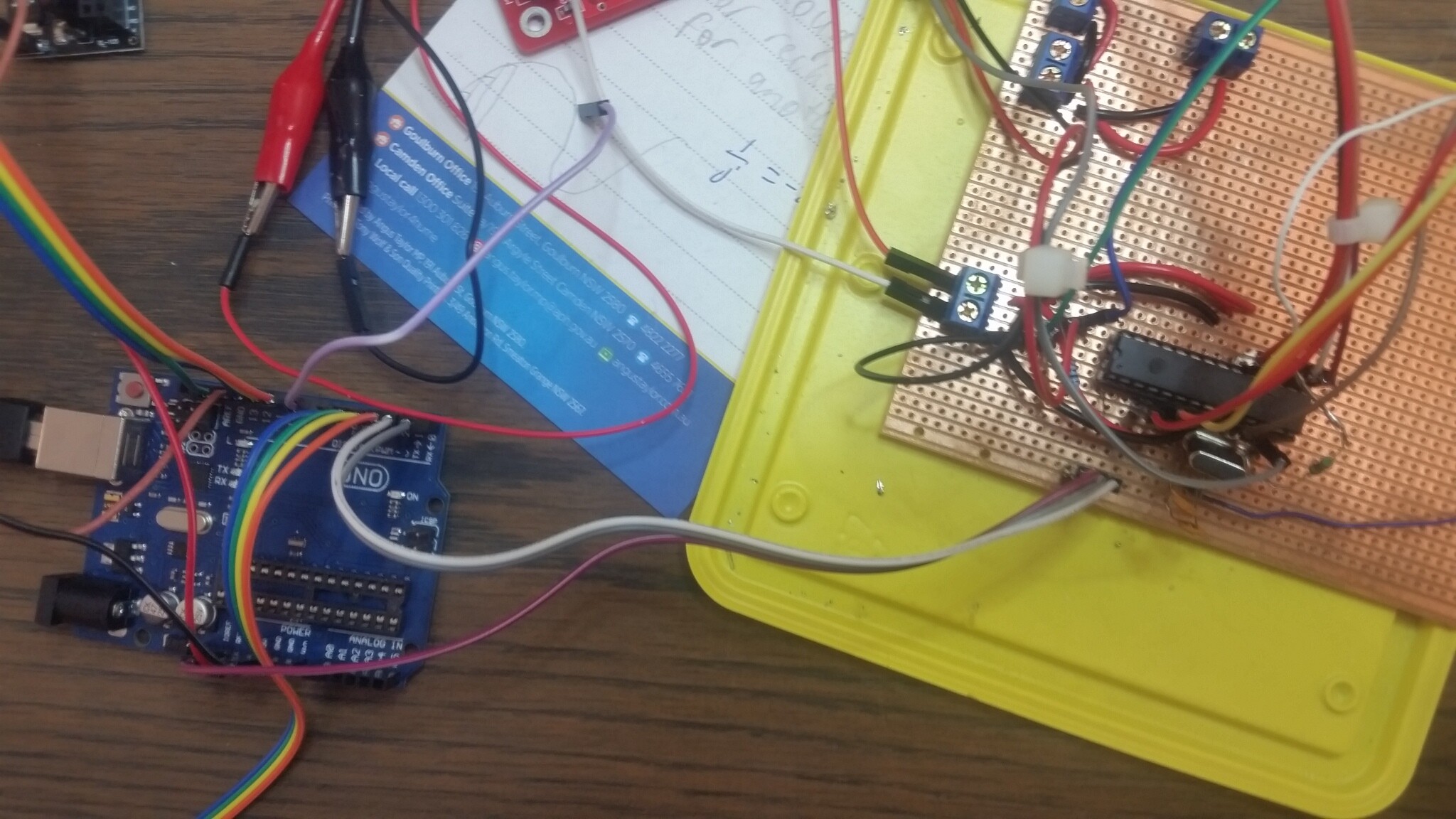
I have also attached a pic of project but it kinda messy so not sure if it helps.
Thanks for the code, but it is not posted correctly, it needs to be pasted into the reply and not attached like you have done unless it is too long. Click on the </> icon at the top left and paste the code between the two braces that pop up.
As to the code I am a bit worried that you are using digital pins to provide power to a device, that is a very bad idea.
As to your problem it looks like the radio library, which uses the same hardware as your Serial print is setting this hardware to another baud rate, so at the least you need to change the serial monitor’s baud rate to match. However you actually need to use software serial to talk to your radio leaving the serial hardware to talk to the monitor.
Yes more strictly the input to the radio is the same piece of hardware as the serial print uses. So the one that is declared last is the one that is used.
Please read the first post in any forum entitled how to use this forum. http://forum.arduino.cc/index.php/topic,148850.0.html . Then look down to item #7 about how to post your code.
It will be formatted in a scrolling window that makes it easier to read.
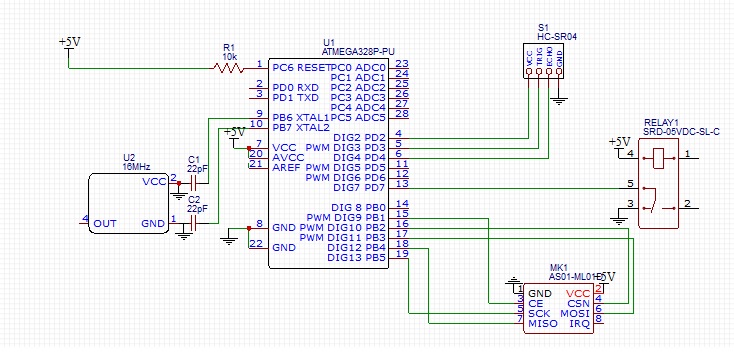
Can you please post a copy of your circuit, in CAD or a picture of a hand drawn circuit in jpg, png?
Thank you for identifying where the conflict/error was occurring, i would not have realized it at all. At least i can now try to work around this issue.
In reply to the previous post i have attached my code in the requested manner. In regards to the circuit diagram, i might have chance tomorrow to draw a basic one up.
#include <SPI.h>
#include <nRF24L01.h>
#include <RF24.h>
#include <RF24_config.h>

//Ultrasonic sensor pins
#define TRIG 3
#define ECHO 4


#define PROX 30

//PINS FOR RELAY SWITCH
#define relaySwitch 7

//PINS FOR radio module
#define CE_PIN   9
#define CSN_PIN 10

RF24 radio(CE_PIN,CSN_PIN);

const byte address[6] = "00001";

int buttonPin = 6;
int buttonState = 0;


void setup() {
// put your setup code here, to run once:
  Serial.begin(9600);

  pinMode(relaySwitch, OUTPUT);
  digitalWrite(relaySwitch, LOW);

  pinMode(buttonPin, INPUT); //button input pin
  digitalWrite(buttonPin, HIGH);//interal pullup resistor?


  pinMode(5,OUTPUT);
  digitalWrite(5,LOW);    //GND for ultrasonic
  pinMode(2,OUTPUT);
  digitalWrite(2,HIGH);    //5V for ultrasonic

  usonicsetup();

  radio.begin();
  radio.openWritingPipe(address);
  radio.setPALevel(RF24_PA_MAX);
  radio.setDataRate(RF24_250KBPS);
  radio.stopListening();

}

void loop() {
  // put your main code here, to run repeatedly:

  buttonState = digitalRead(buttonPin);
//---------------------------------------------------------------------
  //read ultrasonic sensor
  int d;
  d=usonic(11600)/58;  // distance in cm
  if(d==0){d=200;}
  Serial.println(d);    //print d on serial monitor
//----------------------------------------------------------------------


  const char text[] = "nrftest";
  const char text2[] = "noButton";

  if (d<PROX){
    radio.write(&text, sizeof(text));
    //delay(1000);
    Serial.println("PROXIMITY DETECTED");
    digitalWrite(relaySwitch, HIGH);
  }

  if (buttonState == LOW)
  {

    radio.write(&text, sizeof(text));
    //delay(1000);
    Serial.println("buttonState1 = LOW");
    digitalWrite(relaySwitch, HIGH);


  }

  //radio.write(&text, sizeof(text));
  //delay(2000);

  else if ((buttonState == HIGH) && (d>=PROX))
  {

    radio.write(&text2, sizeof(text2));
    //delay(1000);
    Serial.println("buttonState1 = HIGH");
    digitalWrite(relaySwitch, LOW);

  }

  delay(2000);

}


void usonicsetup(void){
  pinMode(ECHO, INPUT);
  pinMode(TRIG, OUTPUT);
  digitalWrite(TRIG, LOW);
}

long usonic(long utimeout){    //utimeout is maximum time to wait for return in us
  long b;
  if(digitalRead(ECHO)==HIGH){return 0;}    //if echo line is still low from last result, return 0;
  digitalWrite(TRIG, HIGH);  //send trigger pulse
  delay(1);
  digitalWrite(TRIG, LOW);
  long utimer=micros();
  while((digitalRead(ECHO)==LOW)&&((micros()-utimer)<1000)){}  //wait for pin state to change- return starts after 460us typically
  utimer=micros();
  while((digitalRead(ECHO)==HIGH)&&((micros()-utimer)<utimeout)){}  //wait for pin state to change
  b=micros()-utimer;
  return b;
}
You show the relay contacts wired as an input to pin 7 and yet in the code you have this pin wired as an output! The relay coil is shown as being connected directly to the power supply and so will be permanent on.
I know you said it is not the same on the diagram as the one you have, but you have to show the wiring correctly.
If indeed you have connected the coil to pin 7 then the very least you need is a reverse biased diode across the coil.
Also the decoupler for 5v is in reference to the reset pin?
You need a capacitor on the reset pin but that is not a decoupling capacitor. A decoupling capacitor goes between 5V and ground.
Aref should go to a capacitor to ground and not be connected to 5V.
Yes Tom I did mention this in reply#1.
Although looking at it again the IC is shown as being placed length ways along the tracks. That means using a scalpel to remove the track between all the holes of the 0.1” pitch device. Something I would never do as rotating the chip by 90 degrees would mean only one breake between adjacent pins.
Thank you for the hints, i see now i was using the wrong side of the vero board (first time).
The back on board looks like the front of board shown by TomGeorge.
Yes i have a multi-meter, i have tested for continuity on all connections (no short circuits happening), and have verified the necessary pins are getting the correct voltages.
But no i have not verified if the DIP socket is shorting on the copper tracks, that is something i will have to check, thank you.
Just to close out this topic, I want to thank everyone for helpful hints.
I managed to resolve all this issues I was having, mainly it was just faulty wiring connections. And there was the issue of the overwriting of the hardware serial from which was solved using software serial.