I need suggestions on how to troubleshoot a new circuit board.
I'm havng a problem getting my first Eagle-designed circuit board to work properly (at all, actually). I have completed a few dozen Arduino/ATMEGA328/ATTINY85 projects, mostly on protoboard. I have successfully etched (someone else's design) circuit boards about 6 times, but this is my first attempt at a sort of "Barebones" Arduino of my own. Please understand that, as a hobbyist, I have some things I understand, but often have huge, gaping holes in my knowledge of electronics.
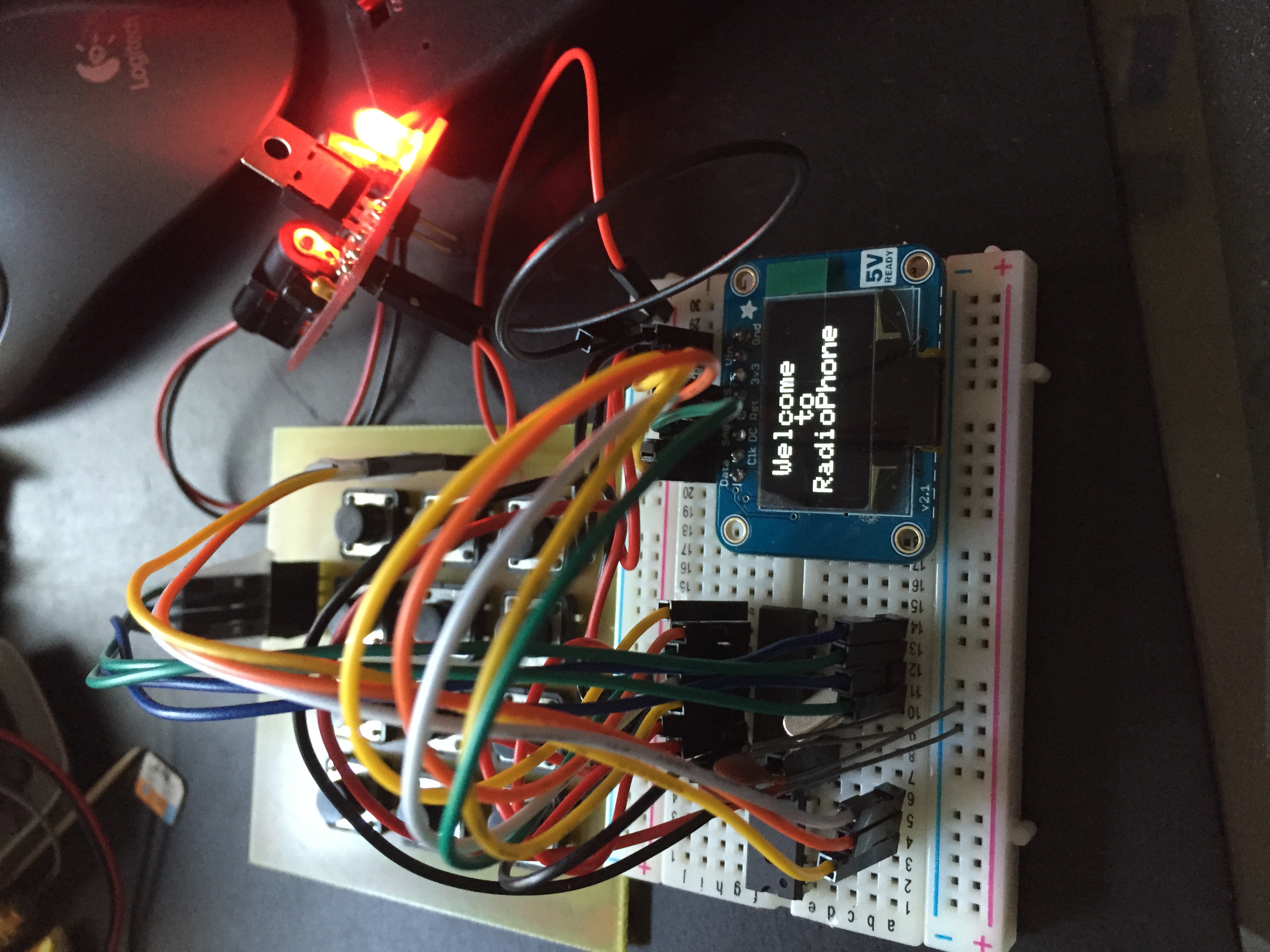
I'm tryng to make a circuit board for a cellphone based on Adafruit's Fona module, a keypad, an OLED display and an ATMEGA328. Currently, I'm only trying to get the OLED and keypad working, and I have this working on a breadboard. The ATMEGA328 program is loaded from an Arduino with a ZIF socket and then placed in the breadboard (see picture). On the breadboard, I only have a 16Mhz crystal, two 22pf caps and a 5V power supply fed by a 9V battery. No other components to make up the circuit - no other capacitors/resistors no reset switch. This breadboard version works to my expectation showing messages on the OLED and with the keypad working.
When I insert the programmed ATMEGA328 into the circuit board version, I don't see any text on the OLED.
What I have done to troubleshoot:
- checked traces for continuity: OK
- checked voltage at all entry points: OK
- fed the IC socket with jumper wires directly from the breadboard version, works! Pin traces are/should be OK
- crudely patched in a 0.1uf ceramic cap between 5V and AREF to GND - no joy
Any help or suggestions gratefully accepted....
atmega328_keypad_v4.pdf (14.2 KB)