Does that happen in sync with the sender, or intermittently?
in sync. i have also tried running robin2's code that tests the connection between arduino and nrf, and this is what i've got.
CheckConnection Starting

FIRST WITH THE DEFAULT ADDRESSES after power on
  Note that RF24 does NOT reset when Arduino resets - only when power is removed
  If the numbers are mostly 0x00 or 0xff it means that the Arduino is not
     communicating with the nRF24

SPI Speedz	= 10 Mhz
STATUS		= 0x00 RX_DR=0 TX_DS=0 MAX_RT=0 RX_P_NO=0 TX_FULL=0
RX_ADDR_P0-1	= 0x0000000000 0x0000000000
RX_ADDR_P2-5	= 0x00 0x00 0x00 0x00
TX_ADDR		= 0x00000000c0
RX_PW_P0-6	= 0x00 0x60 0x00 0x00 0x00 0x00
EN_AA		= 0xc0
EN_RXADDR	= 0xc0
RF_CH		= 0x00
RF_SETUP	= 0x40
CONFIG		= 0xc0
DYNPD/FEATURE	= 0x00 0x00
Data Rate	= 1 MBPS
Model		= nRF24L01+
CRC Length	= 8 bits
PA Power	= PA_MIN
ARC		= 0


AND NOW WITH ADDRESS AAAxR  0x41 41 41 78 52   ON P1
 and 250KBPS data rate

SPI Speedz	= 10 Mhz
STATUS		= 0x00 RX_DR=0 TX_DS=0 MAX_RT=0 RX_P_NO=0 TX_FULL=0
RX_ADDR_P0-1	= 0x0000000000 0x0000000000
RX_ADDR_P2-5	= 0x00 0x00 0x00 0x00
TX_ADDR		= 0x00000000c0
RX_PW_P0-6	= 0xc0 0x60 0x00 0x00 0x00 0x00
EN_AA		= 0xc0
EN_RXADDR	= 0xc0
RF_CH		= 0x00
RF_SETUP	= 0x40
CONFIG		= 0xc0
DYNPD/FEATURE	= 0x00 0x00
Data Rate	= 1 MBPS
Model		= nRF24L01+
CRC Length	= 8 bits
PA Power	= PA_MIN
ARC		= 0


AND NOW WITH ADDRESS AAAxR  0x41 41 41 78 52   ON P1
 and 250KBPS data rate

SPI Speedz	= 10 Mhz
STATUS		= 0x00 RX_DR=0 TX_DS=0 MAX_RT=0 RX_P_NO=0 TX_FULL=0
RX_ADDR_P0-1	= 0x0000000000 0x0000000000
RX_ADDR_P2-5	= 0x00 0x00 0x00 0x00
TX_ADDR		= 0x00000000c0
RX_PW_P0-6	= 0xc0 0x60 0x00 0x00 0x00 0x00
EN_AA		= 0xc0
EN_RXADDR	= 0x00
RF_CH		= 0x00
RF_SETUP	= 0x00
CONFIG		= 0x00
DYNPD/FEATURE	= 0x00 0x00
Data Rate	= 1 MBPS
Model		= nRF24L01+
CRC Length	= 8 bits
PA Power	= PA_MIN
ARC		= 0
i don't really know what to do anymore, i've tried everything almost. i don't know how to confirm if the modules are fried.
i made them work before, conecting them like this. this was when i didn't have 2 batteries. this worked perfectly save for the intermittent contact of the female wires, but when i pressed them it was fine.
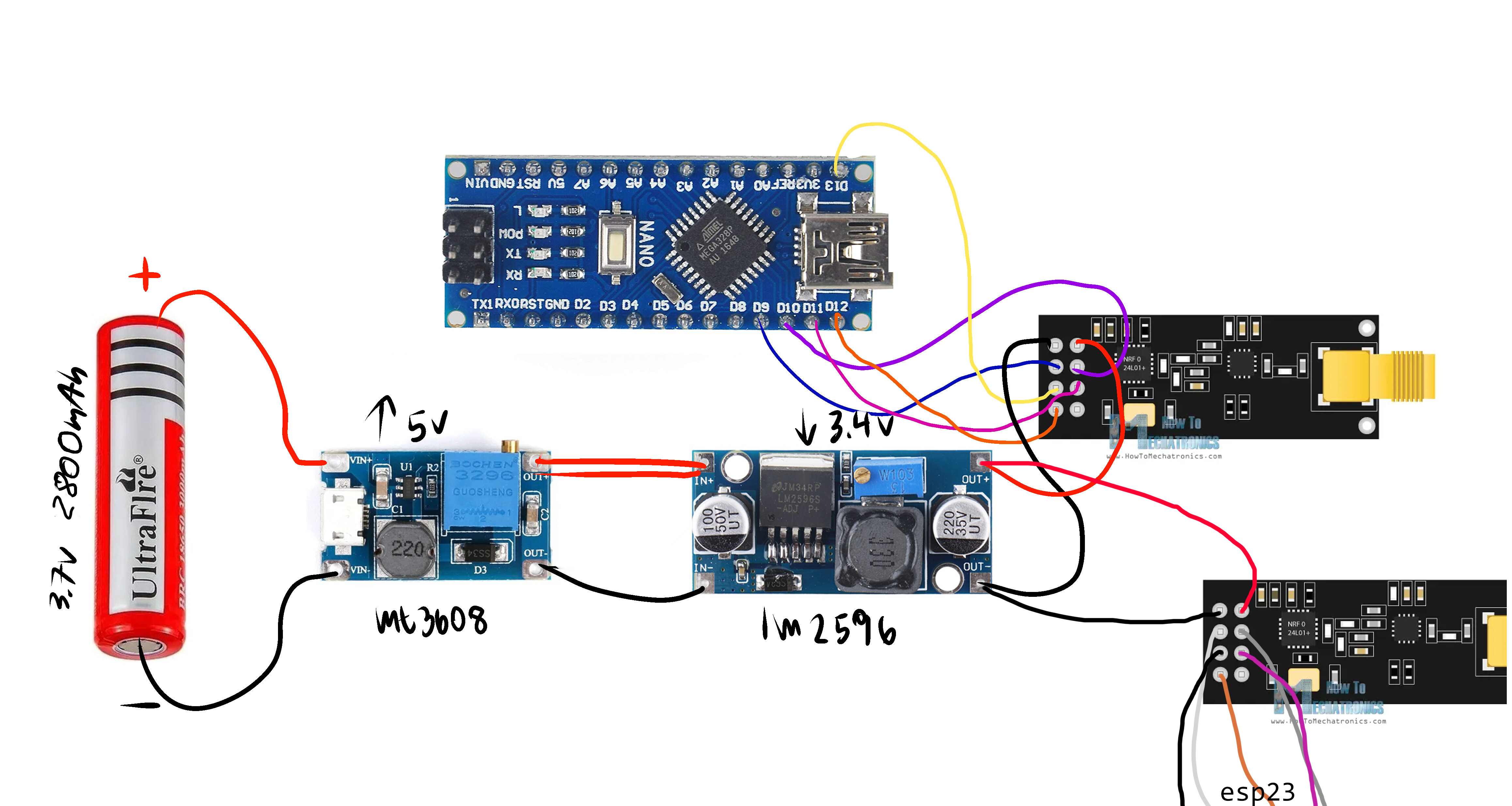
then, i added the gps module.

the arduino and the esp32 arent connected to the stepup, as i'm already powering them with an usb.
when i ran the code like this, one of the wires started melting and smoke started coming out of it. i immediately disconnected the usb and took the battery out of the battery holder. i would think normally think this fried my nrfs or some other component but when i test the voltage everything seems ok, arduino, stepup and stepup are ok.
i have tried the nrfs separated when i bought a new battery and it still worked, though intermittenly, still not sure if it was bc of the poor contact of the female wires.
yet now i don't get anything? not even pressing the wires.
i tried a simpler code.
/*
* Arduino Wireless Communication Tutorial
*     Example 1 - Transmitter Code
*
* by Dejan Nedelkovski, www.HowToMechatronics.com
*
* Library: TMRh20/RF24, https://github.com/tmrh20/RF24/
*/

#include <SPI.h>
#include <nRF24L01.h>
#include <RF24.h>

RF24 radio(7, 8); // CE, CSN

const byte address[6] = "00001";

void setup() {
  radio.begin();
  radio.openWritingPipe(address);
  radio.setPALevel(RF24_PA_MIN);
  radio.stopListening();
}

void loop() {
  const char text[] = "Hello World";
  radio.write(&text, sizeof(text));
  delay(1000);
}
/*
* Arduino Wireless Communication Tutorial
*       Example 1 - Receiver Code
*
* by Dejan Nedelkovski, www.HowToMechatronics.com
*
* Library: TMRh20/RF24, https://github.com/tmrh20/RF24/
*/

#include <SPI.h>
#include <nRF24L01.h>
#include <RF24.h>

RF24 radio(7, 8); // CE, CSN

const byte address[6] = "00001";

void setup() {
  Serial.begin(9600);
  radio.begin();
  radio.openReadingPipe(0, address);
  radio.setPALevel(RF24_PA_MIN);
  radio.startListening();
}

void loop() {
  if (radio.available()) {
    char text[32] = "";
    radio.read(&text, sizeof(text));
    Serial.println(text);
  }
}
in the receiver end i get these simbols:
�����������������������)���& _�w�a�z]�W(�
������
�a�zY�b�ڔ!J�� $�zY�b�ڔ!J�� DD�(��b�ڔ!J��a�zY�b�ڔ!�#����8H� ��XP�A�
I��]�Ց�6
��b15�
�
�8(�� �`�$1�h;�Wt�?c�l�̡'0�=�
8P�"(3
��ƃ� ߡ!���\
�V3��;� DDOW�q,[���
J`�!ġ��\
V3�� "�a� ��W(�Nʈ�Iu� DdOW]�,cPH�&u�"��b��V3�� "�"�*b[�V�&N�%q�
��ED
��c,[p$#����ġ�b[�V����%q�
�%�����\
X��&��%q�a�����\
�b�x��A�������b[���1 �Ѓ;� D�O�+)�N�h oHC M�� �Ŭ��`8� D�O�+)�Nb�1 "� � j�X�7
��
�B͂��
��fv��� Dh��V���A�� ��� ��8�P
�� ] �\��`�1�3 "��EdO�
i tried running robin2's code again after charging the fake battery, my multimeter shows 4.08v. i have running the transmitter on a computer and the receiver on other. this is what my transmitter shows now.
SimpleTx Starting
Data Sent Message 0  Tx failed
Data Sent Message 0  Tx failed
Data Sent Message 0  Tx failed
Data Sent Message 0  Tx failed
Data Sent Message 0  Tx failed
Data Sent Message 0  Acknowledge received
Data Sent Message 1  Tx failed
Data Sent Message 1  Tx failed
Data Sent Message 1  Tx failed
Data Sent Message 1  Acknowledge received
Data Sent Message 2  Tx failed
Data Sent Message 2  Tx failed
Data Sent Message 2  Tx failed
Data Sent Message 2  Tx failed
Data Sent Message 2  Tx failed
Data Sent Message 2  Tx failed
Data Sent Message 2  Tx failed
Data Sent Message 2  Tx failed
Data Sent Message 2  Tx failed
Data Sent Message 2  Tx failed
Data Sent Message 2  Tx failed
Data Sent Message 2  Tx failed
this continues until it reaches 0 again but it isn't consistent. in my receiver end it shows nothing.
Read the link below.
https://forum.arduino.cc/t/simple-nrf24l01-2-4ghz-transceiver-demo/405123
i have tried robin2's code, multiple times as i said before. i tried the old rf24 library that robin specifies in his tutorial, but it doesn't work, it shows an error. when i run the code with the newest rf24 version, at least it compiles the code. external power supply, the same connections, resetting the nrf by disconnecting the power supply, i've read it all. if you want me to read something from the thread specifically please tell me that. also i think the fact that robin didn't update his thread since 2021 is important.
When you mostly see 0x00 or 0xFF in the check connection code, you simply have a wiring issue. It means the MCU and radio are not successfully 'talking'.
This is where you should start looking. Until you get back good data from the radio, there is no point in even trying to transmit or receive data.
It should look something like this:
SPI Speedz	    = 10 Mhz
STATUS		    = 0x0e RX_DR=0 TX_DS=0 MAX_RT=0 RX_P_NO=7 TX_FULL=0
RX_ADDR_P0-1	    = 0x65646f4e31 0x65646f4e32
RX_ADDR_P2-5	    = 0x33 0xce 0x3e 0xe3
TX_ADDR		    = 0x65646f4e31
RX_PW_P0-6	    = 0x04 0x04 0x04 0x04 0x04 0x04
EN_AA		    = 0x3f
EN_RXADDR	    = 0x02
RF_CH		    = 0x4c
RF_SETUP	        = 0x03
CONFIG		    = 0x0f
DYNPD/FEATURE	= 0x00 0x00
Data Rate	    = 1 MBPS
Model		    = nRF24L01+
CRC Length	    = 16 bits
PA Power	        = PA_LOW
ARC		        = 0
From there you, you want to look at adding capacitors, shielding and get your power supply in order. See RF24/COMMON_ISSUES.md at master · nRF24/RF24 · GitHub (scroll down for PA+LNA section)
If you follow the instructions, it will pretty much tell you where your problem is, aside from power supply issues.
i made multiple tests, here's what i got.
circuit 1 (with the lm2596)
citcuit 2 (with the mp1684)
NRF 1 (has a yellow wire)
NRF 2 (has a white wire)
the diagrams of my circuit are on imgur, on post #7
WITH ESP32
NRF 1 CIRCUIT 1
��8 0x00 0x00 0x3c 0x3c 0x20
EN_AA = 0x08
EN_RXADDR = 0x02
RF_CH = 0x3c
RF_SETUP = 0x22
CONFIG = 0x08
DYNPD/FEATURE = 0x78 0x78
Data Rate = 250 KBPS
Model = nRF24L01+
CRC Length = 8 bits
PA Power = PA_LOW
ARC = 0
after disconnecting/connecting
�j�J= 0x000000001c 0x0000000078
RX_ADDR_P2-5 = 0x78 0x78 0x3c 0x1e
TX_ADDR = 0x4040404040
RX_PW_P0-6 = 0x0e 0x20 0x20 0x20 0x20 0x20
EN_AA = 0x18
EN_RXADDR = 0x02
RF_CH = 0x08
RF_SETUP = 0x22
CONFIG = 0xfc
DYNPD/FEATURE = 0x3c 0x3c
Data Rate = 250 KBPS
Model = nRF24L01+
CRC Length = 16 bits
PA Power = PA_LOW
ARC = 8
NRF 1 CIRCUIT 2
AND NOW WITH ADDRESS AAAxR 0x41 41 41 78 52 ON P1
and 250KBPS data rate
SPI Speedz = 10 Mhz
STATUS = 0x0c RX_DR=0 TX_DS=0 MAX_RT=0 RX_P_NO=6 TX_FULL=0
RX_ADDR_P0-1 = 0x0000000000 0x0000000000
RX_ADDR_P2-5 = 0x00 0x00 0x00 0x00
TX_ADDR = 0x0000000000
RX_PW_P0-6 = 0x00 0x00 0x00 0x00 0x00 0x00
EN_AA = 0x00
EN_RXADDR = 0x00
RF_CH = 0x00
RF_SETUP = 0x00
CONFIG = 0x20
DYNPD/FEATURE = 0x30 0x30
Data Rate = 2 MBPS
Model = nRF24L01
CRC Length = 8 bits
PA Power = PA_HIGH
ARC = 0
@=0 MAX_RT=0 RX_P_NO=0 TX_FULL=0
RX_ADDR_P0-1 = 0x0000000000 0x0000000000
RX_ADDR_P2-5 = 0x00 0x00 0x00 0x00
TX_ADDR = 0x0000000000
RX_PW_P0-6 = 0x00 0x00 0x00 0x00 0x00 0x00
EN_AA = 0x00
EN_RXADDR = 0x00
RF_CH = 0x00
RF_SETUP = 0x00
CONFIG = 0x00
DYNPD/FEATURE = 0x00 0x00
Data Rate = 1 MBPS
Model = nRF24L01+
CRC Length = Disabled
PA Power = PA_MIN
ARC = 0
NRF 2 CIRCUIT 1
��0 0x20 0x20 0x20 0x20
EN_AA = 0x3f
EN_RXADDR = 0x03
RF_CH = 0x4c
RF_SETUP = 0x27
CONFIG = 0x1c
DYNPD/FEATURE = 0x00 0x00
Data Rate = 250 KBPS
Model = nRF24L01+
CRC Length = 16 bits
PA Power = PA_M
after disconnecting/connecting
AND NOW WITH ADDRESS AAAxR 0x41 41 41 78 52 ON P1
and 250KBPS data rate
SPI Speedz = 10 Mhz
STATUS = 0x0e RX_DR=0 TX_DS=0 MAX_RT=0 RX_P_NO=7 TX_FULL=0
RX_ADDR_P0-1 = 0x0000001e89 0xc2c2c2c2c2
RX_ADDR_P2-5 = 0xc3 0xc4 0xc5 0xc6
TX_ADDR = 0x3f3f3f9fcf
RX_PW_P0-6 = 0x20 0x40 0x40 0x40 0x40 0x40
EN_AA = 0x3f
EN_RXADDR = 0x03
RF_CH = 0x4c
RF_SETUP = 0x27
CONFIG = 0x0e
DYNPD/FEATURE = 0x00 0x00
Data Rate = 250 KBPS
Model = nRF24L01+
CRC Length = 16 bits
PA Power = PA_MAX
ARC = 15
NRF 2 CIRCUIT 2
j
EN_AA = 0x00
EN_RXADDR = 0x00
RF_CH = 0x00
RF_SETUP = 0x00
CONFIG = 0x00
DYNPD/FEATURE = 0x00 0x00
Data Rate = 1 MBPS
Model = nRF24L01+
CRC Length = Disabled
PA Power = PA_MIN
ARC = 0
after disconnecting
�I� 0x41 41 41 78 52 ON P1
and 250KBPS data rate
SPI Speedz = 10 Mhz
STATUS = 0x0e RX_DR=0 TX_DS=0 MAX_RT=0 RX_P_NO=7 TX_FULL=0
RX_ADDR_P0-1 = 0x3f3f9fcfe7 0xc2c2c2c2c2
RX_ADDR_P2-5 = 0xc3 0xc4 0xc5 0xc6
TX_ADDR = 0xcfcfcfcfe7
RX_PW_P0-6 = 0x00 0x00 0x00 0x00 0x00 0x00
EN_AA = 0x3f
EN_RXADDR = 0x03
RF_CH = 0x02
RF_SETUP = 0x0f
CONFIG = 0x08
DYNPD/FEATURE = 0x00 0x00
Data Rate = 1 MBPS
Model = nRF24L01+
CRC Length = Disabled
PA Power = PA_MIN
ARC = 0
NANO
NRF 2 CIRCUIT 2
FIRST WITH THE DEFAULT ADDRESSES after power on
 Note that RF24 does NOT reset when Arduino resets - only when power is removed
 If the numbers are mostly 0x00 or 0xff it means that the Arduino is not
 communicating with the nRF24
SPI Speedz = 10 Mhz
STATUS = 0xff RX_DR=1 TX_DS=1 MAX_RT=1 RX_P_NO=7 TX_FULL=1
RX_ADDR_P0-1 = 0xffffffffff 0xffffffffff
RX_ADDR_P2-5 = 0xff 0xff 0xff 0xff
TX_ADDR = 0xffffffffff
RX_PW_P0-6 = 0xff 0xff 0xff 0xff 0xff 0xff
EN_AA = 0xff
EN_RXADDR = 0xff
RF_CH = 0xff
RF_SETUP = 0xff
CONFIG = 0xff
DYNPD/FEATURE = 0xff 0xff
Data Rate = 1 MBPS
Model = nRF24L01+
CRC Length = 16 bits
PA Power = PA_MAX
ARC = 15
AND NOW WITH ADDRESS AAAxR 0x41 41 41 78 52 ON P1
and 250KBPS data rate
SPI Speedz = 10 Mhz
STATUS = 0xff RX_DR=1 TX_DS=1 MAX_RT=1 RX_P_NO=7 TX_FULL=1
RX_ADDR_P0-1 = 0xffffffffff 0xffffffffff
RX_ADDR_P2-5 = 0xff 0xff 0xff 0xff
TX_ADDR = 0xffffffffff
RX_PW_P0-6 = 0xff 0xff 0xff 0xff 0xff 0xff
EN_AA = 0xff
EN_RXADDR = 0xff
RF_CH = 0xff
RF_SETUP = 0xff
CONFIG = 0xff
DYNPD/FEATURE = 0xff 0xff
Data Rate = 1 MBPS
Model = nRF24L01+
CRC Length = 16 bits
PA Power = PA_MAX
ARC = 15
AND NOW WITH ADDRESS AAAxR 0x41 41 41 78 52 ON P1
and 250KBPS data rate
SPI Speedz = 10 Mhz
STATUS = 0xff RX_DR=1 TX_DS=1 MAX_RT=1 RX_P_NO=7 TX_FULL=1
RX_ADDR_P0-1 = 0xffffffffff 0xffffffffff
RX_ADDR_P2-5 = 0xff 0xff 0xff 0xff
TX_ADDR = 0xffffffffff
RX_PW_P0-6 = 0xff 0xff 0xff 0xff 0xff 0xff
EN_AA = 0xff
EN_RXADDR = 0xff
RF_CH = 0xff
RF_SETUP = 0xff
CONFIG = 0xff
DYNPD/FEATURE = 0xff 0xff
Data Rate = 1 MBPS
Model = nRF24L01+
CRC Length = 16 bits
PA Power = PA_MAX
ARC = 15
NRF 2 CIRCUIT 1
FIRST WITH THE DEFAULT ADDRESSES after power on
 Note that RF24 does NOT reset when Arduino resets - only when power is removed
 If the numbers are mostly 0x00 or 0xff it means that the Arduino is not
 communicating with the nRF24
SPI Speedz = 10 Mhz
STATUS = 0x00 RX_DR=0 TX_DS=0 MAX_RT=0 RX_P_NO=0 TX_FULL=0
RX_ADDR_P0-1 = 0x0000000000 0x0000000080
RX_ADDR_P2-5 = 0x60 0x00 0x20 0x00
TX_ADDR = 0x0000000060
RX_PW_P0-6 = 0x00 0x60 0x00 0x60 0x00 0x60
EN_AA = 0x00
EN_RXADDR = 0x00
RF_CH = 0x00
RF_SETUP = 0x00
CONFIG = 0x00
DYNPD/FEATURE = 0x00 0x00
Data Rate = 1 MBPS
Model = nRF24L01+
CRC Length = Disabled
PA Power = PA_MIN
ARC = 0
AND NOW WITH ADDRESS AAAxR 0x41 41 41 78 52 ON P1
and 250KBPS data rate
SPI Speedz = 10 Mhz
STATUS = 0x00 RX_DR=0 TX_DS=0 MAX_RT=0 RX_P_NO=0 TX_FULL=0
RX_ADDR_P0-1 = 0x0000000000 0x0000000080
RX_ADDR_P2-5 = 0x60 0x00 0x20 0x00
TX_ADDR = 0x0000000060
RX_PW_P0-6 = 0x00 0x60 0x00 0x60 0x00 0x60
EN_AA = 0x00
EN_RXADDR = 0x00
RF_CH = 0x00
RF_SETUP = 0x00
CONFIG = 0x00
DYNPD/FEATURE = 0x00 0x00
Data Rate = 1 MBPS
Model = nRF24L01+
CRC Length = Disabled
PA Power = PA_MIN
ARC = 0
NRF 1 CIRCUIT 1
FIRST WITH THE DEFAULT ADDRESSES after power on
 Note that RF24 does NOT reset when Arduino resets - only when power is removed
 If the numbers are mostly 0x00 or 0xff it means that the Arduino is not
 communicating with the nRF24
SPI Speedz = 10 Mhz
STATUS = 0x00 RX_DR=0 TX_DS=0 MAX_RT=0 RX_P_NO=0 TX_FULL=0
RX_ADDR_P0-1 = 0x0000000000 0x0000000000
RX_ADDR_P2-5 = 0x00 0x00 0x00 0x00
TX_ADDR = 0x0000000000
RX_PW_P0-6 = 0x00 0x00 0x00 0x00 0x00 0x00
EN_AA = 0x00
EN_RXADDR = 0x00
RF_CH = 0x00
RF_SETUP = 0x00
CONFIG = 0x00
DYNPD/FEATURE = 0x00 0x00
Data Rate = 1 MBPS
Model = nRF24L01+
CRC Length = Disabled
PA Power = PA_MIN
ARC = 0
AND NOW WITH ADDRESS AAAxR 0x41 41 41 78 52 ON P1
and 250KBPS data rate
SPI Speedz = 10 Mhz
STATUS = 0x00 RX_DR=0 TX_DS=0 MAX_RT=0 RX_P_NO=0 TX_FULL=0
RX_ADDR_P0-1 = 0x0000000000 0x0000000000
RX_ADDR_P2-5 = 0x00 0x00 0x00 0x00
TX_ADDR = 0x0000000000
RX_PW_P0-6 = 0x00 0x00 0x00 0x00 0x00 0x00
EN_AA = 0x00
EN_RXADDR = 0x00
RF_CH = 0x00
RF_SETUP = 0x00
CONFIG = 0x00
DYNPD/FEATURE = 0x00 0x00
Data Rate = 1 MBPS
Model = nRF24L01+
CRC Length = Disabled
PA Power = PA_MIN
ARC = 0
NRF 1 CIRCUIT 2
0-6 =�CheckConnection Starting
FIRST WITH THE DEFAULT ADDRESSES after power on
 Note that RF24 does NOT reset when Arduino resets - only when power is removed
 If the numbers are mostly 0x00 or 0xff it means that the Arduino is not
 communicating with the nRF24
SPI Speedz = 10 Mhz
STATUS = 0x00 RX_DR=0 TX_DS=0 MAX_RT=0 RX_P_NO=0 TX_FULL=0
RX_ADDR_P0-1 = 0x0000000000 0x0000000000
RX_ADDR_P2-5 = 0x00 0x00 0x00 0x00
TX_ADDR = 0x0000000000
RX_PW_P0-6 = 0x00 0x00 0x00 0x00 0x00 0x00
EN_AA = 0x00
EN_RXADDR = 0x00
RF_CH = 0x00
RF_SETUP = 0x00
CONFIG = 0x00
DYNPD/FEATURE = 0x00 0x00
Data Rate = 1 MBPS
Model = nRF24L01+
CRC Length = Disabled
PA Power = PA_MIN
ARC = 0
AND NOW WITH ADDRESS AAAxR 0x41 41 41 78 52 ON P1
and 250KBPS data rate
SPI Speedz = 10 Mhz
STATUS = 0x00 RX_DR=0 TX_DS=0 MAX_RT=0 RX_P_NO=0 TX_FULL=0
RX_ADDR_P0-1 = 0x0000000000 0x0000000000
RX_ADDR_P2-5 = 0x00 0x00 0x00 0x00
TX_ADDR = 0x0000000040
RX_PW_P0-6 = 0x00 0x00 0x00 0x00 0x00 0x00
EN_AA = 0x00
EN_RXADDR = 0x00
RF_CH = 0x00
RF_SETUP = 0x00
CONFIG = 0x00
DYNPD/FEATURE = 0x00 0x00
Data Rate = 1 MBPS
Model = nRF24L01+
CRC Length = Disabled
PA Power = PA_MIN
ARC = 0
is there a reason why my esp32 shows those weird numbers? and why my nano doesn't communicate with my nrfs? i don't think it's fried, i have used it recently to test my gps module.
I'm having trouble following which output is for which device.
I think you are having success with the ESP32, but the nano is just not communicating with the module, so either you have bad wiring there or something else is wrong with the nano/rf24 device.