I will try to make this circuit give me a moment and I will post my result here.
Thank you
I will try to make this circuit give me a moment and I will post my result here.
Thank you
Your sentence makes no sense. An LED has two terminals. The cathode or negative terminal, and the anode or positive terminal. A common cathode seven segment display has all 8 cathodes connected together internally. A common anode display will have all 8 anodes connected together internally.
There is no “segment side” or “digit side”, just the ten pins as shown above.
Hello
I was also facing the same issue. My friend advised me that for driving a 5-digit 7-segment display using an Arduino Uno and serial communication, we can use the "SevSeg" library. On the hardware side, we can use the MAX7219 or MAX7221 driver ICs along with the Arduino Uno to simplify the process of controlling the display.
Thank you .
Hi,
This is very simple. To display values from a PC on a 5-digit 7-segment display using an Arduino Uno, you can use the "SevSeg" library, which provides easy control for multiplexed 7-segment displays. All you need to do is Install the library in your Arduino IDE first to simplify programming and display manipulation.
Regarding the hardware, using the MAX7219/MAX7221 (max72xx) LED driver can be advantageous. It allows for easier control of multiple digits and reduces the number of pins required to drive the display. Connect the MAX7219/MAX7221 to the Arduino Uno using the SPI interface, and follow the library documentation to interface with the display.
With the SevSeg library and MAX7219/MAX7221, you can efficiently display values received from the PC through serial communication on the 5-digit 7-segment display.
Thanks ![]()
Yes, it does make sense. With multi-digit displays, it is normally the digit pins that determine whether the display is CC or CA. If the digit pins are cathodes, the display is CC.
@raffy0991 is already using that, see post #35.
Not with the display @raffy0991 is using. It requires at least 12V supply and those chips have 5V maximum. It may be possible to use those chips with additional driver circuits for higher voltages, but this becomes complex.
Should both be used?
@gregbowers and @ashishroe
please read again what the TO has available.
A MAX7219 can not be used without further measures for a 12V display.
Feel free to link MAXIMs application note with proposals how to use a 12V 7 segment with the MAX7219, or link to several other threads which were already discussing that.
But please don't just throw in an IC (which was already suggested long ago before the TO has provided the 12V information) after you should know that the TO wants to drive a 12V display.
If you are using the MAX7219/MAX7221 LED driver, you can directly interface it with the Arduino Uno using the SPI interface and follow the driver's documentation to control the display. In this case, you may not need to use the SevSeg library. However, if you prefer to use the SevSeg library for its simplicity and convenience, you can use it without the MAX7219/MAX7221 LED driver.
But you could use SevSeg library with MAX7219 if you prefer?
I have simulated it in proteus giving the LED in the drawing a value of 10v 100mA (assuming the current consumption needs 100mA). I will try to make it in actual tomorrow if I can. Also, I could not recreate the diagram you gave me where you have a 4k7 and 10k on the base of bc327. The LED does not turn on on proteus.
Hi,
Yes I have looked in to Max7219 but it does not drive 12 V LED array 7 segment. I have researched it and it needs a udn2891 or uln 2803 or other circuit to drive it. I have already used the SevSeg. Now my only problem is the LED driver circuit.
Hi I was just referring to the 7 segment display and the way I tested it so that it is easier to understand. since the 7 segment display and the SevSeg library referred it as segment pins and digit pins.
Change R4 to 220R. This will allow ~20mA to flow into the base of the NPN, putting it into saturation even when all 8 segments of a digit are lit at the same time.
Move R2 to be between the PNP and the LED.
Why not? What happened when you tried?
About R2:
For segments A-F, which have 6 LEDs in series, the value should be (12 - 6x1.8)/0.020 = 60R. So use a 68R resistor.
For the decimal points, which have only 3 LEDs in series (as far as I can make out), the value of R3 should be (12 - 3x1.8)/0.020 = 330R
I'm assuming the forward voltage of these LEDs is about 1.8V and the desired current is around 20mA.
My bad, I assumed he was talking about one display, not an assembly. Now it makes a little more sense. The information I provided is still the best way to think about it, in my opinion. It gets right down to the definition of CA or CC. If you learn this you will better understand the whole circuit.
Hi this based on my calculations I hope I am not mistaken. These are the resistor values based on the given Beta of the transistor 2n2222 = 100 and 2n5401 = 50 and the assumed forward voltage of 1.8 V and 20 mA. (Note: I have not included the "digit side" transistors since I am still checking the correct resistor value). The part that I don't understand is the R11. With or without the R11 it will still turn on the LEDs. Does it have a significant impact or can I remove this from the circuit?
Change R4 to 220R. This will allow ~20mA to flow into the base of the NPN, putting it into saturation even when all 8 segments of a digit are lit at the same time.
Why is it 20 mA? I assumed if all the 8 segments will turn on it is about 20mA x 6 leds x 8 segments? Not really good at this calculations. Apologies
In this circuit, you are using the transistors as switches rather than amplifiers. So you want to put them into the "saturation region" to minimise their voltage drop. In the saturation region, the gain will be much lower than the Beta values from the datasheet, which is the gain in the "linear" region. If you assume a low gain of, say, 10, you can calculate resistor values which should put the transistor into that saturation region.
I don't understand it either, but it is often shown in example circuits. Maybe another forum member can help us understand if it truly plays an important role.
No, it will be 20mA x 8 segments in parallel = 160mA. The same 20mA flows through all 6 of the LEDs in a segment because they are in series. So 160mA is the current that will flow from collector to emitter of the npn. R4 controls the current flowing from base to emitter. To get the transistor into saturation (where gain could be as low as 10) you need around 16mA flowing into the base. The exact resistor value is not critical because the gain doesn't change much with small changes in current when in the saturation region, and the gain could be higher than the assumed 10.
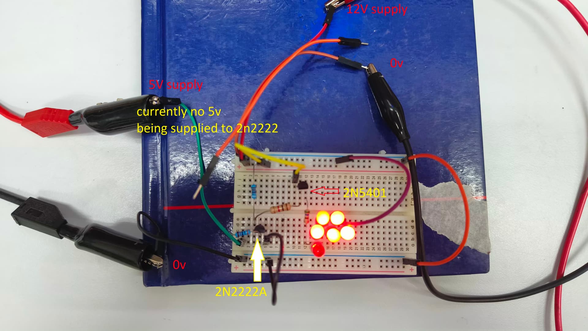
So I have tested the circuit in real time based on the circuit I posted above and this what happened. The LED keeps turning on even if no 5v supply in the base of 2n2222. (note: all the resistors have change because I played with different resistor values because I thought it would solve the problem). I checked the 2n2222 circuit, without the 2n5401 circuit, the switching of 2n2222 has no problem it turns on the LED when i supplied 5V to its base. Now, I also tried 2n5401 circuit, without the 2n2222 circuit, before I could put the resistor to ground and touch the leg of the resistor the LED will turn on (as shown on the picture). I think there is a problem with my 2n5401 circuit and I don't know how to solve it.