In the Arduino IDE I tried clicking both "Burn bootloader" or "Upload using programmer" - but both fail with the same error shown above. I was using "Serial UPDI 230400 baud" programmer.
On my cable I see TXD LED blink a few times, which makes me think it's at least trying to talk to attiny, but it still ends with the error.
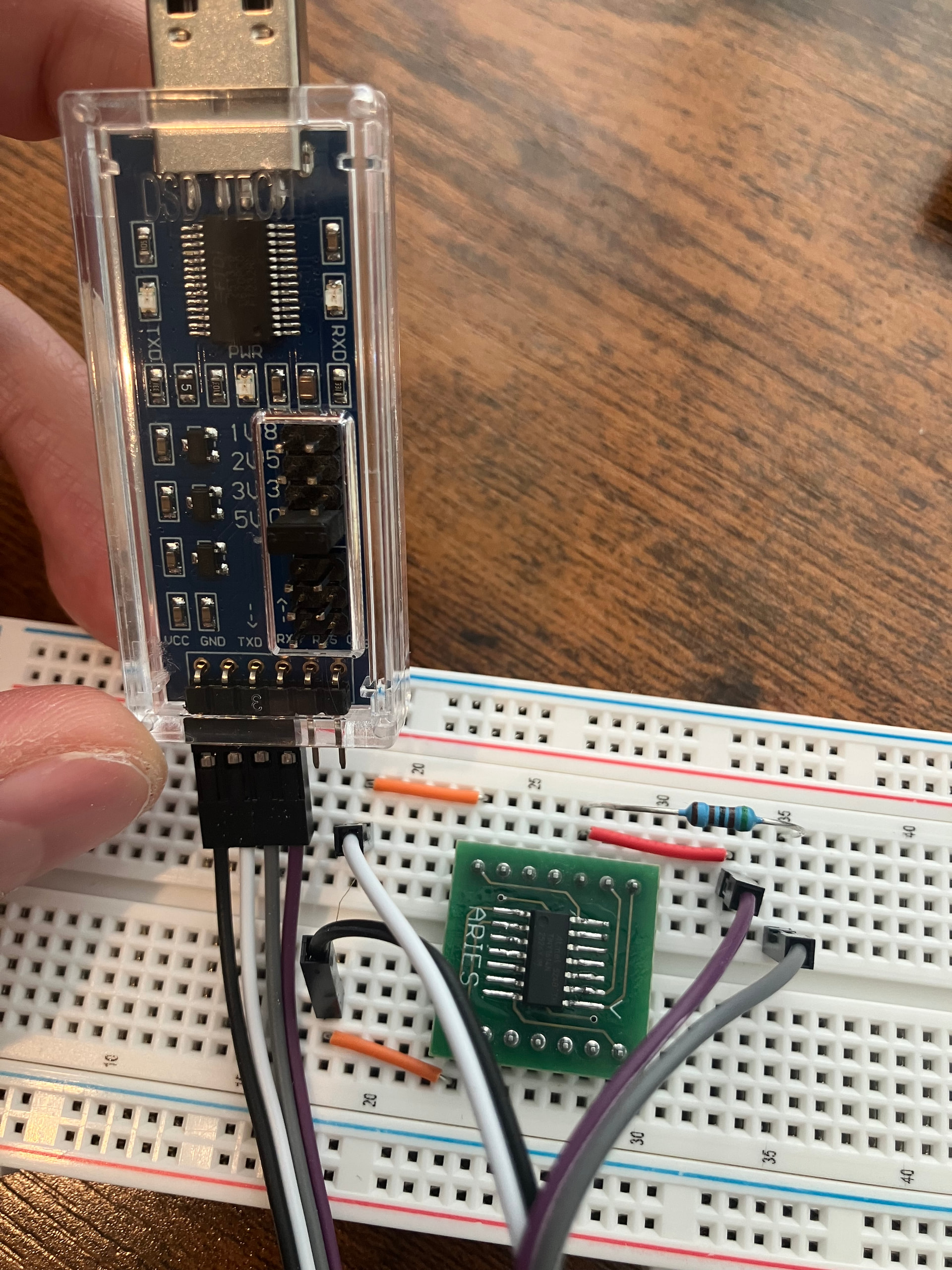
Here is what I’ve tried so far (no luck with any of these):
Checked my soldering: I soldered attiny to breadboard adapter myself. But then I checked using a multimeter that there is near zero resistance between each pin of attiny and corresponding breadboard output. I also checked that there are no bridges between each adjacent pair of pins.
Checked voltage with multimeter: attiny is indeed getting the right voltage from USB to TTL UART Converter Cable. When powered on.
Tried different options in Arduino IDE:
SerialUPDI Slow 57600 baud programmer
jtag2updi programmer - this one doesn't appear to do anything and doesn't even print any error message. But yet another YouTube tutorial suggested to try it, but I think they are using a different device to program.
Other options in Tools menu, like clock speed, bod voltage level, etc.
Different wiring options - that's what ChatGPT suggested, not sure if it hallucinated all of that.
Added .1 uF capacitor between VCC and GND
Added 10k resistor between ATtiny pin 10 (UPDI) and VCC
Tried to set voltage in USB to TTL UART Converter Cable to either 3.3V or 5V.
So I have a few questions to the experts:
Is there anything obviously wrong in my setup? What else should I try? What additional tests can I conduct to debug this?
Is my hardware noob-friendly? I mean Attiny 1614 and USB to TTL UART Converter Cable? Are there more noob-friendly versions? I've heard other people use Arduino to program attiny chips - should I try that approach?
Is there a detailed noob-friendly tutorial that is known to work?
Well they appear to be soldered in on the bottom. You can see more photos from different angles on Amazon product page.
And I also verified with multimeter that at least there is voltage between VCC and GND.
Is there also an easy way to test that there is a signal on TXD and RXD?
I just ordered diodes - will try in a few days when the package arrives.
Idle state of UART is usually high, so you should also see a voltage between each of those pins and GND.
Sometimes there is a bare minimum of solder on the underside and it doesn't always show through to the top. I did check some online images and in most of them you can make out at least some solder topside, so it did make me wonder. If they are soldered at the bottom then they are probably OK.
Sometimes it comes down to luck with the choice of usb/uart adaptor. Some may have resistors in the TX/RX paths and sometimes the TX/RX leds are powered directly from the TX/RX pins affecting their use as a updi programmer. In the latter case, removing the leds (or their series resistors) helps.
You can follow the story here which includes successes and failures with a selection of such adaptors. Yet another UPDI programmer Mk II
EDIT
The FTDI FT232RNL chip used on the USB/UART chip in the OP is unlikely to drive the leds directly from the TX and RX pins because other pins on the chip can be configured to drive the leds. Dataheet (PDF): https://ftdichip.com/wp-content/uploads/2022/07/DS_FT232RN.pdf.
Where did the idea to use a single 5.1k resistor originate ?
This didn't work, same error message. Although I substituted 470R with 440R - the closest one I could make given what resistors I have. Hope that shouldn't make much difference. I also tried using 1N5817 instead of 1N4148 - still no luck. But actually with this setup my FTDI device blinks both TXD and RXD leds, instead of only TXD, not sure if there's a clue.
Also tried this, also didn't work.
I also ordered module CH342 USB-2TTL that you recommended from Ali express - it will arrive in a week and I'll try again.
Missing in the video but you've mentioned it in your text is the 100nF ceramic capacitor across the power rails of the ATTINY1614. This is necessary for decoupling and should be as close as possible to the chip. When I use such a breakout board as you have, I often solder it directly between pins 1 and 14 on the top of that board.
Sometimes you can get away without it but you should anyway have it, especially since you are having problems.
Ok, I figured it out. Turns out there were two problems:
Either soldering issue or during my previous experiments I must have bricked my soldered ATTiny. I bought a Pomona test clip for SOIC-14 and inserted a brand new ATTiny1614 into it. At this point it still didn't work though.
Software issue. I am on Windows and it automatically detected my FTDI device - and COM port created by it. So I thought it didn't require any additional drivers. But then I read the booklet that came with it (RTFM) and it said I had to install the drivers from some Chinese website. Surprisingly enough when I ran the installer, it told me that all my drivers are up-to-date and nothing needs to be installed. But somehow COM port changed its number from COM5 to COM4. So something must have changed. And then everything works like magic.
Next time I guess I should use Linux...
As for electrical wiring I used the one I found in my original tutorial: without any diodes but with 5k1 resistor and 100nF capacitor.
Anyway, thank you for help, guys!