Hello, I want to change the frequency of the speedometer signal of a motorcycle and feed the changed signal to a cruise control. At the moment, I am directly wiring the speedometer signal and the cruise control to the Arduino pins. As soon as the engine runs, the output frequency is getting very inconsistent. I think usage of opto-couplers instead of direct connections could help. The Speedometer signal is a square wave with an amplitude of around 4.5 V. The cruise control is itself a microcontroller and accepts speedometer signals with amplitudes between 4V and 14V. Do I need any additional resistors at the output opto-coupler?
You need some capacitors to filter both the Arduino power and the signals. Capacitor at the Arduino input will remove any fast spikes that have perhaps been coupled by the ignition circuit.
What value? It depends on the signal you have to pass. I would start with a 0.1µf and if the signal is reduced too much go to a 0.01µF
Opto-coupler isolate electrically but they will transfer fast signals.
As JohnRob said you need to filter the signal. There are online RC filter calculators that you can use. Just use Google "rc filter calculator". Choose a capacitor and the cut off frequency and the calculator will give you the required resistor value.
Klaus is correct, I should have added a series resistor before the capacitor. For your situation a 10K in series with the input and just the capacitor on the output. Calculating the RC is probably not too helpful since you don't know exactly what you are trying to filter.
Another good design option is to keep all the wires coming to and from the Arduino (including the power) kept in one bunch. And all the grounds common.
Now the opto's. In an automobile the "ground" (should be common) can vary 2 volts from the battery negative. Although there are other ways to accommodate this variation an opto could be useful. I can't imagine in a motorcycle such a large variation exists.
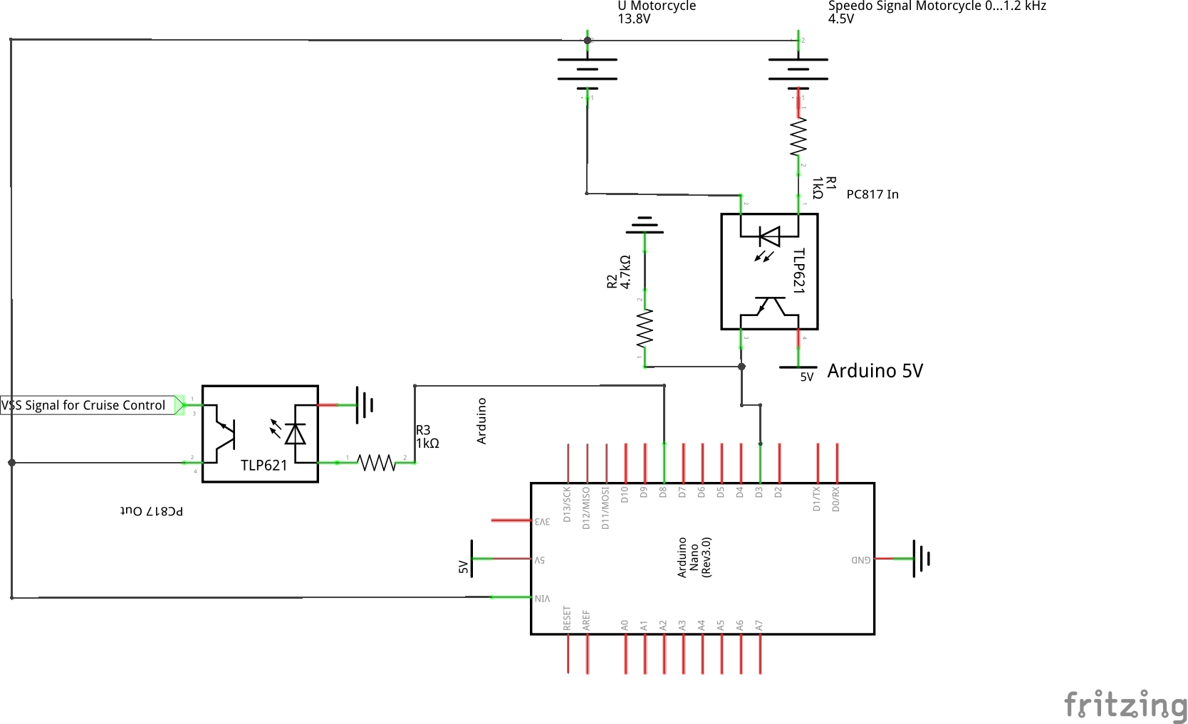
Thank you for the answers. It helps me a lot. I don't really understand where to put the capacitor and the resistor for the low pass filter. Is this correct:
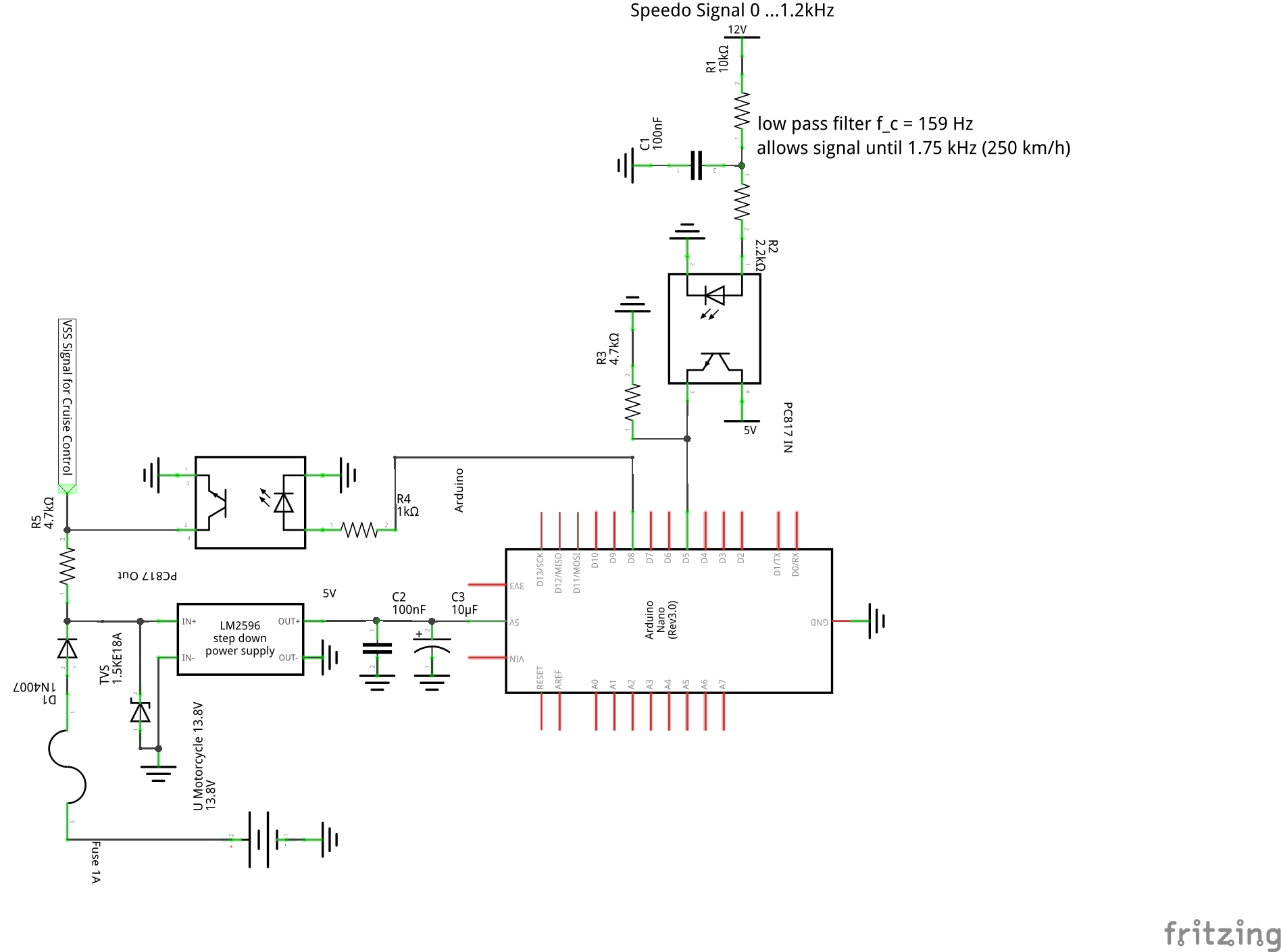
I need to get the input signal between 120 Hz (17.5 km/h) and 1.2 kHz (175 km/h). Therefore, I think a cutoff frequency of 1.59 kHz would be correct, so I have to use a 10 kΩ resistor and a 10 nF capacitor or a 1kΩ resistor and a 100 nF capacitor.
Is it a good idea to use a LM2596 DC-DC converter to provide 5 V instead feeding 13.8 V from the Battery/Alternator to VIN?
I have realized that speedometer signal amplitude is 12 V, not 4.5 V.
I would add a capacitor near the board Vin and Gnd.
I didn't mention it but leads and wires are your enemy (when it comes to noise). Its best to keep caps very close to the Arduino input pins AND connect all the caps to the same ground pin on the Arduino. Actually ALL ground connections to the Arduino should be on the same pin. If not you run noise currents through the board.
If all the processor is doing is what you've shown I wouldn't use a switching setpdown powersupply. They add more noise and are better for high current applications.
Something like a L7805CV (from ST) is good for 35 Volts in. Should be find for your application. Look at ebay for either the device or a small board with the device and capacitors.
Remember the cutoff frequency is a sine wave. A 1.2kHz square has higher frequency components. If you have an oscilloscope check the signal. You still want to have a nice rising edge.
Arduinos do not have automotive grade protection circuits. You should look into this. I have seen users describing their Arduinos fate when connected to their cars electrical systems without protection. Boom.
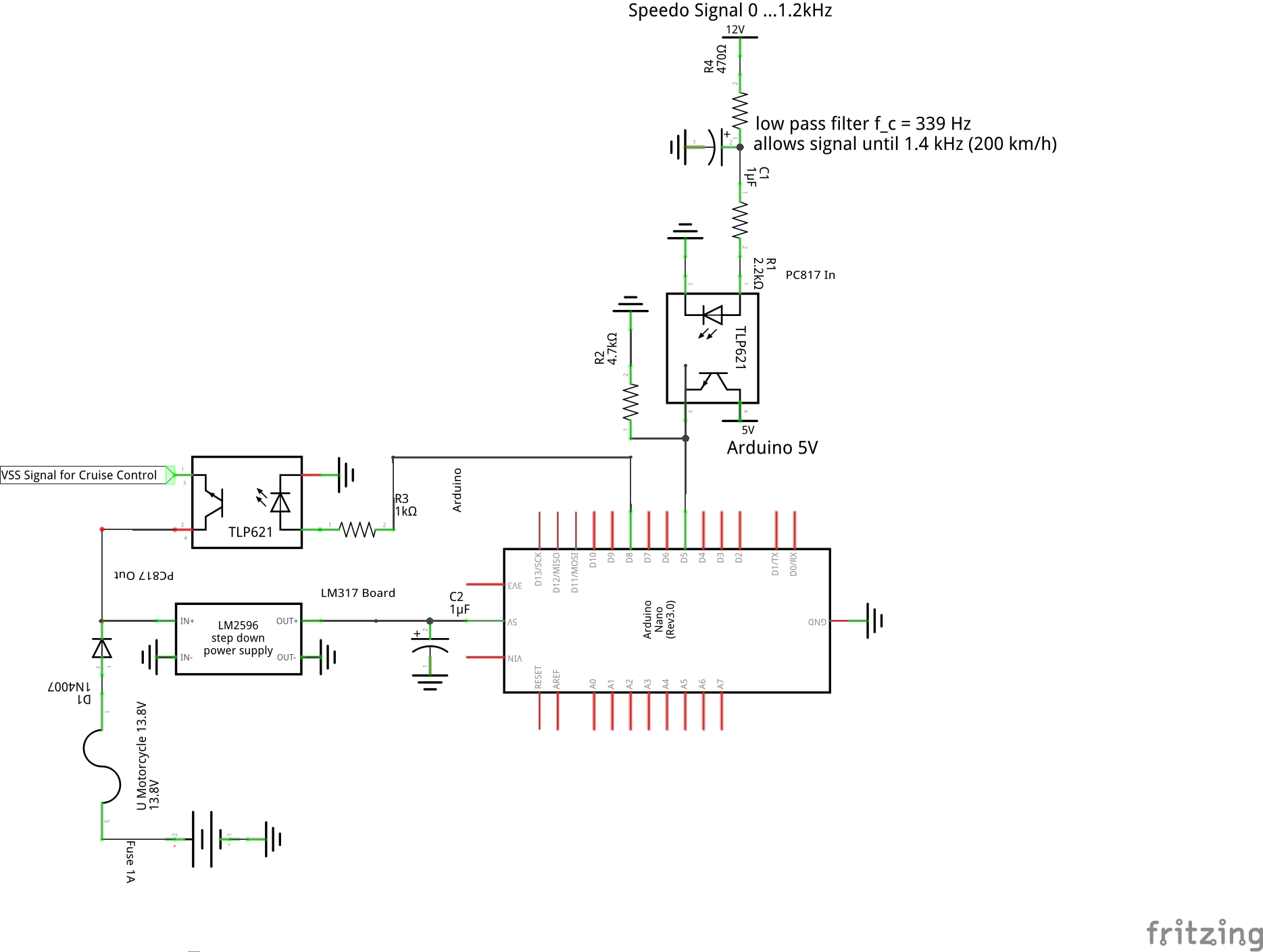
Thank you for the additional answers. I tried out different cutoff frequencies and found that even at a cutoff frequency off 339 Hz the Arduino can reliable detect input frequencies up to 1.4 kHz (210 km/h) which is more than enough. My DSO150 oscilloscope shows the wave is not a nice square signal anymore, but that does not matter to just get the frequency.
I will but the low-pass filter before the opto-coupler so the noise is not amplified. I don't have ceramic capacitors at home, is there a problem using a 1 µF electrolytic capacitor instead of the recommended 0.01 µF or 0.1 µF ceramic capacitor when I adjust the resistor?
To the problem of automotive power input: I think big voltage spikes should not happen as long as the battery and rectifier are in good shape. As far as I know, the ABS and engine ECU can also be damaged if there are any spikes. My voltmeter always shows 13.8 V while driving and a bit less while idling. I don't have a L7805CV at home and ordering takes long, so I will use a LM317 board and use a diode at the input (if some reason the polarity is reversed). Is a 1 µF electrolytic capacitor between the 5V and GND pin of the Arduino correct? Should I add more protection?
I will put the Arduino in a metal candy box and use an Ethernet cable for the four wires. I will then solder the cable shielding to box and connect the box also to ground.
I think the 1µF is marginal for really fast spikes, but it might be OK since this a motorcycle.
What capacity would be a appropriate?
If this were a vehicle I would vehemently disagree with you on this point. However for a Motorcycle, I don't have any experience.
I have never connected an oscilloscope, I have only a fixed installed voltmeter, so you are probably right. Is the source of the spikes the ignition system? Then there should not be a difference between a car and a motorcycle. I can connect tomorrow my DSO150 to check it.
Its not the capacity but the type. Electrolytic capacitors are good for energy storage but have a lot of inductance and do not react "fast enough" for high frequency spikes.
Note: "fast enough" is not technically correct but communicates the characteristic.
Spikes come from:
Ignition
Lights going on and off
Starting engine (starter + ignition)
Shutting engine down
Like I said, your 1µF will likely be fine. Its just not what I would design into a device.
I was able to get some 100 nF ceramic capacitors. My LM317 board is damaged and the ordered L7805CV did not arrive until now so I just tried the not recommended LM2596 board. It works nows. Thanks for all the help.
I'm now using the following code based on arduino-projects/freq_count.ino at master · onetransistor/arduino-projects · GitHub to not only divide the frequency by 8 but also apply a linear function to allow the cruise control to engage at 25 km/h instead of 40 km/h. I calculate the mean of 5 samples to make the signal more smooth for the cruise control:
// Arduino frequency converter based on:
// Arduino frequency counter from a few Hz up to 6 MHz
// One Transistor, 2018
// https://www.onetransistor.eu/
//
// Based on:
//  * Frequency Counter sketch by Nick Gammon (CC BY 3.0 AU)
//    http://www.gammon.com.au/timers
//  * FreqCounter library by Martin Nawrath (LGPL 2.1)
//    http://interface.khm.de/index.php/lab/interfaces-advanced/arduino-frequency-counter-library/

// set sampling period here (in milliseconds):
#define DEBUG
#define N_SAMPLES 5  // size of circular buffer for measured impulses

const unsigned int samplingPeriod = 50;  // in ms

// Timer 1 overflows counter
volatile unsigned long overflow1;

volatile unsigned int out_pulse_us = 0;
unsigned long last_time_out;
bool current_state_out = LOW;

#ifdef DEBUG
unsigned long last_time_print = 0;
#endif

const float M = 0.889;
const float K = 17.8;
const byte OUT_PIN = 8;

unsigned int samples[N_SAMPLES];  // circular buffer for samples
unsigned short samples_index = 0;

void init_Timer1() {
  overflow1 = 0; // reset overflow counter

  // Set control registers (see datasheet)
  TCCR1A = 0; // normal mode of operation
  TCCR1B = bit(CS12) | bit(CS11) | bit(CS10); // use external clock source

  TCNT1 = 0; // set current timer value to 0

  TIMSK1 = bit(TOIE1); // enable interrupt on overflow
}

ISR(TIMER1_OVF_vect) {
  overflow1++; // increment overflow counter
}

// Timer 2 overflows counter
volatile unsigned int overflow2;

void init_Timer2() {
  overflow2 = 0; // reset overflow counter

  GTCCR = bit(PSRASY); // reset prescalers

  // Set control registers (see datasheet)
  TCCR2A = bit(WGM21); // CTC mode
  TCCR2B = bit(CS22) | bit(CS20); // prescaler set to 1/128, "ticks" at 125 kHz
  OCR2A = 124; // counts from 0 to 124, then fire interrupt and reset;

  TCNT2 = 0; // set current timer value to 0

  TIMSK2 = bit(OCIE2A); // enable interrupt
}

// interrupt happens at each 125 counts / 125 kHz = 0.001 seconds = 1 ms
ISR(TIMER2_COMPA_vect) {
  if (++overflow2 < samplingPeriod) // add an overflow and check if it's ready
    return; // still sampling

  samples[samples_index] = (overflow1 << 16) + TCNT1;
  unsigned long totalSamples = 0;
  for (unsigned short i=0; i<N_SAMPLES; i++) {
     totalSamples += samples[i];
  }


//  float freqHz = (float)totalSamples / (float)N_SAMPLES * 1000. / samplingPeriod;
//  float kmph_in = freqHz * frq_const_in;  //  1.933 m/s (wheel circumflex) == 6.9588 km/h -> 6 Hz (measured), -> v = frq * 6.9588/6 == frq * 1.1598 (frq_const_out);  48 pulses, 1.95m -> .14625 (frq_const_in)
//  float kmph_out = (kmph_in * M + K);  // from Excel
//  float frq_out = kmph_out * (1 / frq_const_out);
//  out_pulse_us = 500000 / frq_out;  // there is a low and a high pulse -> divide by 2 -> 1e6/2 == 5e5*/
//  out_pulse_us = 500000 * .14625 * 1/((((overflow1 << 16) + TCNT1) * 1000. / samplingPeriod) * .14625 * 0.889 + 17.8)
//  out_pulse_us = 500000 * frq_const_out / (((overflow1 << 16) + TCNT1) * 1000. / samplingPeriod * frq_const_in * M + K)
//  out_pulse_us = 500000 * frq_const_out / (((overflow1 << 16) + TCNT1) * 130. / samplingPeriod + 17.8);
//  out_pulse_us = 579900. / (((overflow1 << 16) + TCNT1) * 3.25 + 17.8);  // correct
//  out_pulse_us = 500000 * frq_const_out / ((float)totalSamples / (float)N_SAMPLES * 1000. / samplingPeriod * frq_const_in * M + K);
//  out_pulse_us = 500000 * 1.1598 / ((float)totalSamples / 5 * 1000. / 50 * .14625 * 0.889 + 17.8);
  out_pulse_us = 579900. / ((float)totalSamples * .520065 + 17.8);

  // reset timers
  TCNT1 = 0; overflow1 = 0;
  TCNT2 = 0; overflow2 = 0;
  samples_index++;
  if (samples_index >= N_SAMPLES) {
    samples_index = 0;
  }
}

void setup() {
  for (int i=0; i<N_SAMPLES;i++)  {
    samples[i] = 0;
  }
  #ifdef DEBUG
  Serial.begin(115200);
  Serial.println("Arduino Frequency Converter");
  Serial.println();
  last_time_print = millis();
  #endif

  // Disable Timer0; millis() will no longer work
  //TCCR0A = 0; TCCR0B = 0;

  // start timer 1 (count frequency)
  init_Timer1();
  init_Timer2();
  pinMode(OUT_PIN, OUTPUT);
  last_time_out = micros();
}

void loop() {
  if((micros() - last_time_out) > (out_pulse_us - 8)) {  // 8us for delay
      last_time_out = micros();
      byte new_state = (byte)(!current_state_out);
      digitalWrite(OUT_PIN, new_state);
      current_state_out = new_state;
  }
  #ifdef DEBUG
  if((millis() - last_time_print) > 1000) {  // print every second
      last_time_print = millis();
      Serial.print("out_pulse_us: ");
      Serial.print(out_pulse_us);
      Serial.print(" us (");
      unsigned int freq = 1000000/(2*out_pulse_us);
      Serial.print(freq);
      Serial.print(" Hz, ");
      Serial.print(freq * 7 / 6);
      Serial.println(" km/h)");
  }
  #endif

}