Unfortunately the pump is always on but when pin 11 goes to HIGH it has more power (moving faster), so it never goes completly off. What did I do wrong?
Thanks in advance.
Please read the post at the start of any forum , entitled "How to use this Forum".
What is the power supply that the pump is supplied, what voltage.
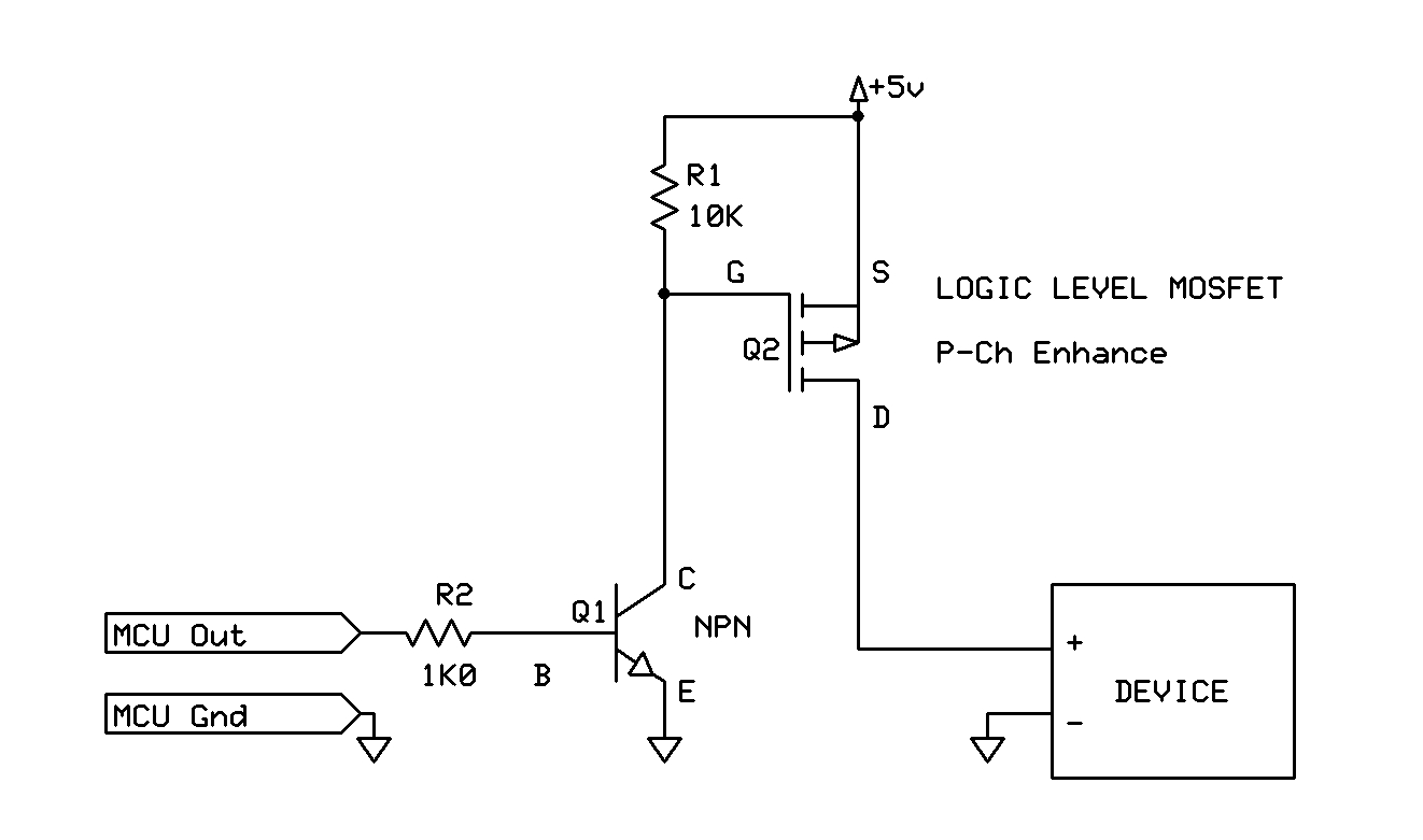
As you are high side switching your circuit will only function if Vcc to the pump is 5V
Is there a reason to high side switch?
Low side switching would be easier.
Hey Tom,
sorry saw my mistake with the Voltage and edit it 2 min before you replied. Its a small pump and its working fine with the connected LiPo (normal LiPo .. so around 3.7 - 4.2V)
Why High? Because I had these MOSFETs Laying around and use one in combination with an DS3231 to power the board, see here: Low Active 2A Switch (and I just copied the design )
Hi,
With 3V3 output you will not be able to switch the P-CH MOSFET OFF, because the gate will be at 3V3 and the source at 5V.
So you still have 3V3 - 5 = - 1.7V Vgs
Hi,
Looking at your schematic, where are you getting power for the UNO and what is the purpose of the UNO?
Why have you a Vcc2 and another P-CH MOSFET connected to the UNO Vref?
What is your project supposed to do?
Have you breadboarded it and tried it in full?
I tested everything and it worked fine, but maybe the LED I used for the Pump was slightly on all the time but I didnt see it. (using pumps without Water is not a good idea) And yes maybe I should have tested this part more. Everything else is working
So the big question is, can I make a quick fix of my stupid mistake
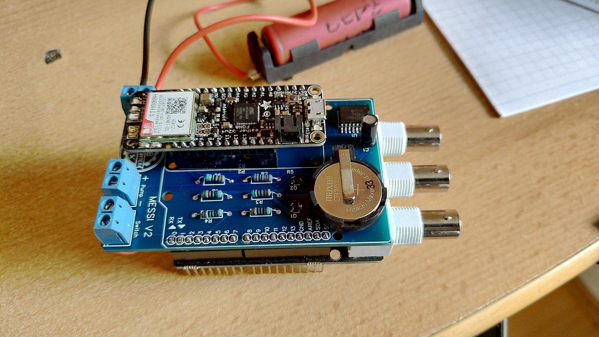
Its a water test station for a lake and it is sending the PH, Temp and oxygen values to a server over GSM. This is Version 2.. version 1 was much much bigger and a lot more cables
And sorry when its confusing, I am softwaredeveloper so working with code is easy for me, working with "voltages" is more an adventure
But I did a similar pcb for a security door watcher and this also is working, but it didnt have the controlable pump switch. I see my problem now, the Voltage of the Feather is not high enough for the MOSFET to stop... but now I have to find a fix for that
The SQW-PIN of the DS3231 goes to GND when an Alarm is triggered. (you can set 2 Alarms in the DS3231) in this case at full hour and at :30. So when this happens, my Feather turns on.
And if you say something like: yeah there is an enabler pin... yes but this doesnt work so stable with the fona.
So in the end: the data will be send every 30 minutes.