Hello.
I have tried to follow an arduino example (Pushbuttonstoggleledsshiftregmultiplexer).
This example it´s in examples (control surface/examples.old/medium.old/extendedinputoutput/)
I don´t know what am i doing wrong..if someone could help me..

No led lighting on any multiplexer pin press.
Here its the example code
/**
* @brief This example demonstrates the use of push buttons and LEDs and how
* to use shift registers and analog multiplexers to save pins.
*
* Connections:
*
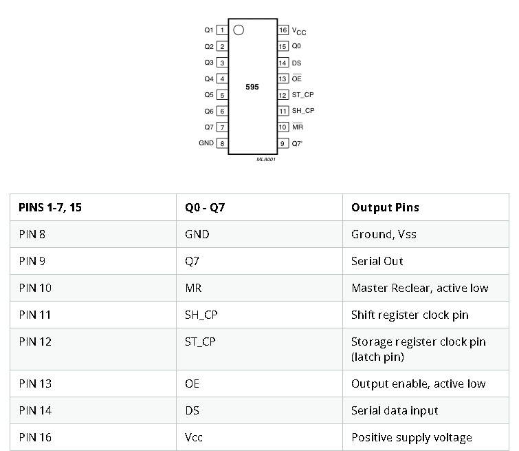
* - 10: 74HC595 ST_CP
* - 12: 74HC595 DS
* - 13: 74HC595 SH_CP
* - 18: 74HC4067 A (COM OUT/IN)
* - 19: 74HC4067 S0
* - 20: 74HC4067 S1
* - 21: 74HC4067 S2
* - 22: 74HC4067 S3
*
* Connect 16 momentary push buttons between the input pins of the
* multiplexer and ground.
* The internal pull-up resistor for the buttons will be enabled automatically,
* so no external resistors are necessary.
*
* Connect 16 LEDs (and series resistors) between the eight outputs of the
* two shift registers and ground.
*
* Remember to connect the enable pins of both the multiplexer and the shift
* register to ground in order to enable them.
* Connect the serial data output of the first shift register (QH' or Q7S) to
* the serial input of the second shift register.
*
* Pressing the first button will turn on the first LED. Pressing it again will
* turn it off again.
* Pressing the second button will turn on the second LED. Pressing it again will
* turn it off again, and so on.
*
* Written by PieterP, 2018-08-28
* https://github.com/tttapa/Control-Surface
*/
#include <Control_Surface.h> // Include the Control Surface library.
/* Instantiate a multiplexer with three address lines. */
CD74HC4067 mux = { 8, {2, 3, 4, 5} };
/* The number of buttons and LEDs */
constexpr size_t n = 16;
const pin_t latchPin = 10; // Pin connected to ST_CP of 74HC595
const pin_t dataPin = 11; // Pin connected to DS of 74HC595
const pin_t clockPin = 12; // Pin connected to SH_CP of 74HC595
/* Instantiate a shift registers on the correct pins, most significant bit
* first, and a total of 16 outputs (two eight-bit registers). */
ShiftRegisterOut<n> sreg = { dataPin, clockPin, latchPin, MSBFIRST };
/* Instantiate the momentary push buttons.
* It generates an array of Buttons on pins:
* { mux.pin(0), mux.pin(1) ... mux.pin(15) } */
auto buttons = generateIncrementalArray<Button, n>(mux.pin(0));
void setup() { /* Initialize everything. */
mux.begin();
sreg.begin();
for (Button &button : buttons)
button.begin();
}
void loop() { /* Check if a button is pressed, if so toggle the LED. */
for (uint8_t i = 0; i < n; ++i)
if (buttons[i].getState() == Button::Falling)
sreg.digitalWrite(i, !sreg.digitalRead(i));
}
Thanks.