That is wrong.
Voltage and current are two aspects of the same thing. You can't have one without the other.
So a common reference serves for both.
Get one thing right and you automatically get the other correct.
I am impressed how many ways people find to get things wrong.
Why do you think this is weird?
A simple schematic would have sorted this out in the first few posts, instead of all that verbiage you posted in the original question.
You connect a PWM signal direct to 12V and you will burn things. You connect it to 12V through a resistor and while it might appear to work now it will probably fail a lot sooner that it normally would. Maybe after a month or year it is hard to tell.
That is fine that should make no difference. The fact that you are seeing a difference is telling me you still have it wrong somewhere.
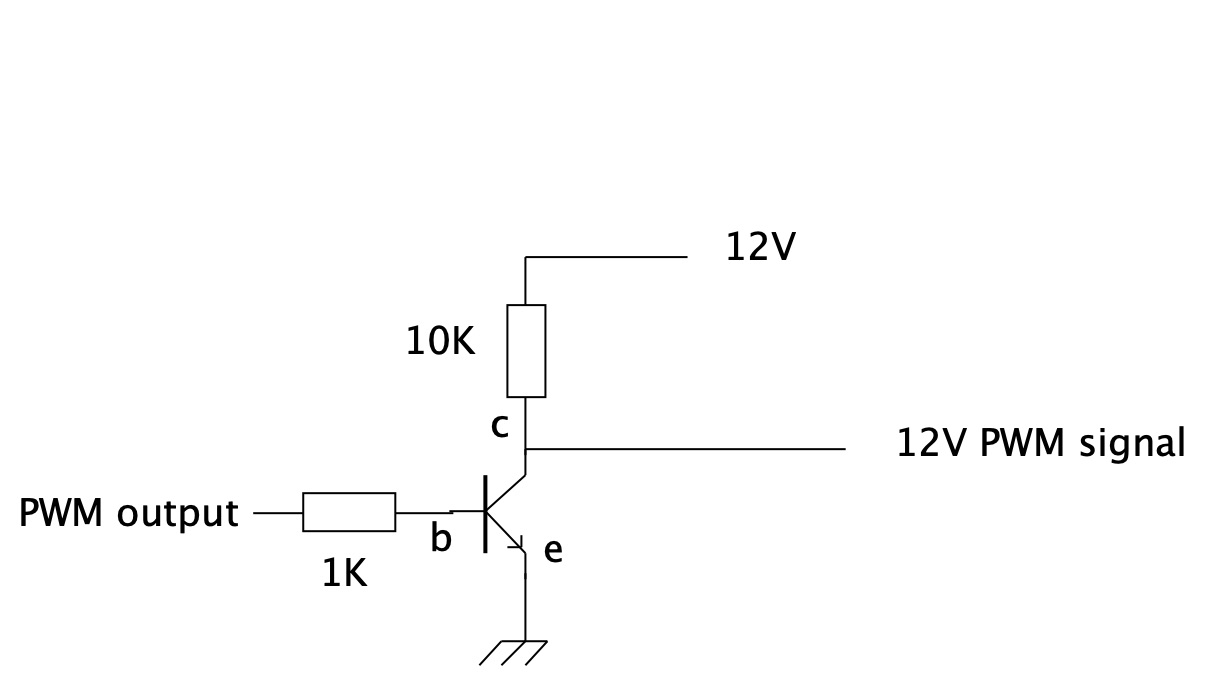
To get the PWM signal to a 5V level you connect the PWM pin to a 1K resistor with the other end of a resistor to base of an NPN transistor. You connect the emitter of the transistor to the common ground.
To the collector of the transistor connect a 10K resistor with the other end of the resistor going to the +12V of the supply. Finally the place where the resistor and the collector is connected together is the place where you have a 12V PWM signal. Or without the verbiage, like this:-
Those LED drivers can't take a 12volt PWM signal.
While the LED supply could be 8-30volt, logic input must stay below 5volt.
I suspect people burned their ESP pin because they did not have a common ground for the logic.
Leo..
Do we have a part number for that chip, rather than just a rather useless link to a board? Are we sure that the board he is using has a PT4115 in it. If so you are correct and that circuit I just posted is wrong.
Indeed that could be true as the photograph of the soldered up board shows nothing connected connected to the ground pin.
Digging a bit deeper I found that this is not the regular LED driver schematic configuration as I assumed in previous posts. It's a buck converter with current feedback. The chips is an XL4001. Here is the datasheet, page 4 has the circuit.
The chip is PWM-ed with the EN pin, and switch points are 0.8volt and 1.4volt (>1.4 = on).
I think I would prefer a PT4115E board over this one, but they seem to have disappeared over the years. Sparkfun still has good (picobuck/femtobuck) LED drivers with that principle, at a price.
Leo..
The reason for thinking its weird with the PWM pin to the chip is that a previous commenter started that this is the usual way this kind of chip is hooked up, but that should mean that it would run fine off 3.3v PWM signal / there should be no need for the 1k resistor. Yet it seems there was.
Now I see further down a suggestion that the issue might just have been the missing common ground and that could ofc very well be the case.
With regards to the PWM input voltage I don't think it should be 12v into it.
I actually did also wire the separate ground pin for the PWM afterwards to give it a shot. It's doesn't effect the behavior. I didn't test it without the 1k resistor though out of fear of burning another board..
It seems you can put a PWM voltage into this board equal to the LED supply,
but it is not needed to do so. 3.3volt PWM is just fine.
You can also keep the 1k resistor in series. it has no negative effect on behaviour.
If inverted PWM bothers you, then you can fix it this way. analogWrite (ledPin, (1024 -pwmValue)); // invert 10-bit PWM of an ESP8266
Leo..
@t0ppy
You seem not to have discovered the edit icon or something. There is no need to have a separate reply for each person, just use the @name of the person and then your comments to them.
Thank you. Thats exactly what i did. Just as far as I understood it doesn't really invert the signal - like the phase is different or something. But again I might be misunderstanding.
I didn't say otherwise so I'm not sure why you're pointing this out in a reply to me?
Maybe I'm misunderstanding, but that's not quite right. You could have a circuit with the right voltage, but the wrong resistance and wrong current. Just because you have one thing right doesn't mean it's automatically correct.
Yes you are totally misunderstanding things here.
Current can only flow when there is a potential difference between two points. With no common reference there is no way you can have a voltage between two points. Any measurements you might take are meaningless. In fact the act of trying to make the measurement between two unconnected points disturbs the system and creates for the duration of that measurement high impedance between the two totally separate systems.
I think this shows that fundamentally you do not understand how electricity works. That sentence is a nonsense, worthy of Alice in wonderland.
Of course you said otherwise.
I pointed out that indeed they are the same thing.
Which is why I am saying you fundamentally do not understand how electricity works. Ohms law can only apply in a complete system, which without a common reference, you do not have.
I've deleted a couple of things to remove some of the disagreement that's getting a bit heated. Please remember this is @t0ppy 's topic and replies should be ones that help him / her.