Want to drive Chinese Power supply, Has Mach 3 pwm @0-10VDC to control Mill Motor speed with RAMPS board 1.4 (looks to be capable of controlling 5VDC PWM) . Mega 2560 R3 controller.
Thinking I can drive this off of Aux1 pins, but it is only capable of handling 5v.
Looking to control another PWR with my RAMPS board 1.4, (Thinking that my RAMPS board 1.4 will not handle the 10v)
PWR supply states that it needs a low @ 0v high @ 10v PWM signal.
Do I use a step-up voltage converter, Mofset or is there a better solution?
Look for FET Driver ICs.
They are basically a schmitt trigger input and totem pole output.
They are made to drive power MOSFETs with fast rise and fall times.
??? confused, this is only info I can find:
【INPUT PWM SIGNAL】The module can input PWM signal to control motor speed, lamp brightness and so on.
【WIDE APPLICATION】The output can control high-power equipment, bulb, LED strip, DC motor, micro pump, solenoid valve, etc.
Specification:
Product model: YYNMOS-1
Input signal: 3~20V PWM signal
Output capacity: DC 3.7V~27V, current ≤ 10A
PWM frequency: 0~1kHz
Wiring terminal description:
DC+: DC power supply positive
DC-: DC power supply negative
PWM: Signal input terminal (connected to the single-chip IO port, PLC interface, DC power supply, etc.)
GND: Signal negative terminal
OUT+: Output positive terminal (connected to the device positive)
OUT-: Output negative terminal (connected to the device negative)
To my logic, it takes 0-5v input and controls 0-10v output, granted that it probably a 2/1 ratio.
Was there an issue or stumbling block with planned approach?
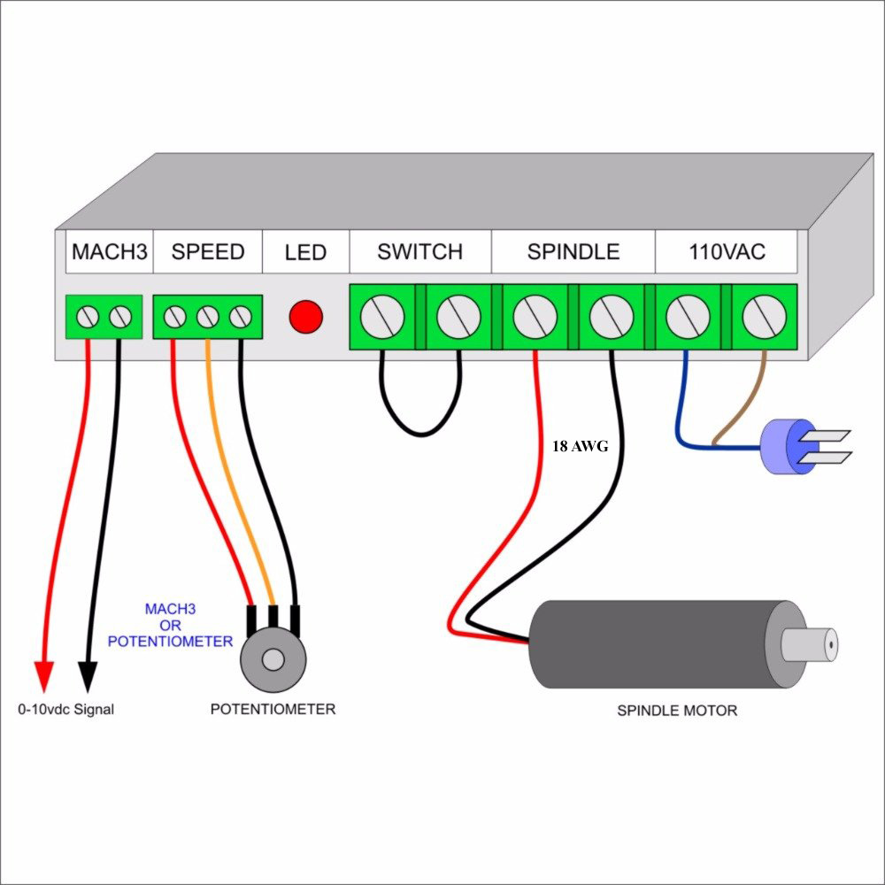
From the diagrams it doesn’t look to use a PWM input , just a voltage provided by the pot.
Wire it up as per their example and measure the input voltages from that pot
Your circuit won’t work and could damage something.
I expect you will need to go from your micro’s 0-5v PWM ( analog out) signal , through a stage to convert that to 0-10v ( transistor switch using 10v supply); then a smoothing circuit to create a steady analog voltage to input to that psu.
As I said with the circuit supplied with the unit , you can see how the input varies, make your Arduino circuit produce the same voltage range - then connect the two together- if you bodge about there is a good chance of breaking something .
Google how the “analog “ output from the processor works