I am trying to build a test circuit for a DC motor. It seems that i will need a motor controller that outputs a variable voltage based upon something. The something is a feather huzzah which outputs an SDA and SCL signal. Is one of these SDA or SCL signal going to be a DC voltage ? Lets say that it is the SDA. Is this signal going to be a rapidly fluctuating DC voltage that will cause the motor to spin either faster or slower ?
If i were able to adjust my DC power supply fast enough, could i accomplish the same thing ?
To output a defined DC voltage, you need a digital to analog converter (DAC).
SCL and SDA are signals required for I2C connections, and could be used to control a DAC module. But that DAC will not be able to provide power for a motor.
hextejas:
Is one of these SDA or SCL signal going to be a DC voltage ?
Yes. All voltages provided by the ESP8266 are DC.
hextejas:
Is this signal going to be a rapidly fluctuating DC voltage
Well, it's digital communication, which means the line will rapidly be switching between 3.3 V (or whatever the voltage is of the power rail the pull-up resistors are connected to) and ground.
hextejas:
that will cause the motor to spin either faster or slower ?
Certainly not directly. You could never control a motor directly from an I2C bus. You might find a motor driver that uses I2C communication between the driver and the ESP8266, but you would be sending messages to the motor driver, which it then interprets and controls the voltage to the motor accordingly. I'm not aware of such a driver. The DRV8871 driver I used in a project was controlled by PWM.
Please bear with me folks as I attempt to understand this. The project that I am trying to build is meant to drive 2, Radio Controlled, servo motors. These servo motors are DC and controlled by this board.
So, I was wondering what the SDA and SCL signals had to do with the board. Do they turn it on and off ?
Using a VOM, it read that the full voltage, 6.6 was available on all of the 16 V+ pins.
I have no idea what the 16, PWM pins are supposed to be doing.
Is there some logical connection between the SDA, SCL pins and the PWM pins ?
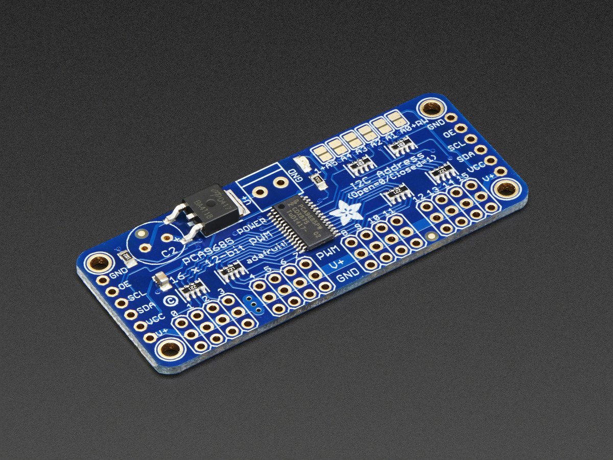
I2C is how a microcontroller (i.e. Arduino) talks to the PCA9685 chip to tell it what to output on the PWM pins.
Servos don't really use PWM. They expect a 1000 to 2000 microsecond wide control pulse occurring at a 50 Hz rate.
1000 would be turned all the way to one side, 2000 all the way to the other. That control pulse is typically at 0/5V levels, controllable directly from a 5V Arduino.
PWM on the other hand can be any frequency, with variable duty cycle.
From its datasheet " The PCA9685 operates with a supply voltage range of 2.3 V to 5.5 V and the inputs and outputs are 5.5 V tolerant."
If you are seeing 6.6V I'd be concerned about something being damaged.
CrossRoads:
I2C is how a microcontroller (i.e. Arduino) talks to the PCA9685 chipIf you are seeing 6.6V I'd be concerned about something being damaged.
Thank you Crossroads and as an aside, I think that you need to write a new book, "Arduino for Idiots" and dedicate it to me. :=)
I said it wrong, the voltage was really 5.5
CrossRoads:
I2C is how a microcontroller (i.e. Arduino) talks to the PCA9685 chip to tell it what to output on the PWM pins.
Downloads | Adafruit PCA9685 16-Channel Servo Driver | Adafruit Learning SystemServos don't really use PWM.
Still trying to understand this. The connectors to the servos are 3 output pins, +, GND, and PWM. From 0 thru 15.
So if servos dont really use PWM, what's with PWM in the connector ?
Is the + within the 0-15, either on or off based upon some other signal, like SDA or SCL ? Or is it always on ?
I have 2 servos, numbered 0 and 1. So something within my Arduino code is going to tell each of them to be either on or off and for how long (I am guessing).
In my simple case, to me it would make sense that the 0-15 pins would be off until I needed the servo to move.
And then "something" would turn it on, IE, make it 5V. The servo move just fine when I put a +5v directly to it.
I can see that I need a tutorial on PWM stuff.
thanks again.
Servos DO use PWM, and I don't understand why Crossroads thinks otherwise.
The neutral servo position is specified by a pulse width of 1.5ms, while the extremes are typically 1.0 and 2.0 ms wide. The pulse repetition rate is about 50 Hz.
That control specification is most certainly PWM, pulse width modulation.
If you read the Adafruit tutorial for that PCA9685 board you should be able to get a better understanding of what is going on. Give it a try and ask again for anything you don't understand.
Also note that the code to drive servos using that board is VERY different from the normal code used to drive servos directly from the Arduino. I don't know why you are using the PCA9685 for only 2 servos because most Arduinos can easily drive 2 servos without the added complexity of the PCA9685 but that's up to you.
Steve
Okay, maybe I should have said a very limited version of PWM, with a 1-2mS wide pulse at a 50Hz rate.
Vs controlling an LED for example, where the frequency is much higher, and the pulse widths vary a lot more for controlling brightness, or for creating a DC-ish voltage where the PWM width is low-pass filtered to make DC levels.
8 2500µsec "channels" fit into the 20000µsec refresh time, so you can control 8 different servo channels on 1 radio frequency (channel).
JCA34F:
8 2500µsec "channels" fit into the 20000µsec refresh time, so you can control 8 different servo channels on 1 radio frequency (channel).
And at least in the RC world that composite signal is usually called PPM (Pulse Position Modulation) which isn't really very helpful either.
Steve
Okay, maybe I should have said a very limited version of PWM, with a 1-2mS wide pulse at a 50Hz rate.
The sort of PWM you control a servo motor with is not the same PWM you get out of an Arduino with an analogWrite command.
Is the + within the 0-15, either on or off based upon some other signal, like SDA or SCL ? Or is it always on ?
The chip on that board generates a PWM signal that can be made to look like any sort of PWM. So you can make it look like the PWM to drive a servo motor.
So, I was wondering what the SDA and SCL signals had to do with the board. Do they turn it on and off ?
The SDA and the SCL signals generate the I2C interface.
You change the numbers inside the chip by sending it a message through the I2C interface. These numbers determine the shape of the PWM signal that is produced.
Once you have written these the PWM produced keeps the servo at a fixed specific angle. To change the angle the servo is pointing at you have to change these numbers. There’s a library that makes these things easy.
A servo will not rotate continuously unless you modify it inside. Once you do it is no longer a servo but a continuous rotation servo. With these you can not specify the angle it points, only the direction and speed of rotation are controllable.
You should never connect the data input to 5V.
You can avoid using that board from Adafruit by using the servo library on the Arduino. This allows any Arduino pin to produce a signal that is suitable to drive a servo.