I am trying to output text to a QR204 thermal printer using an Adafruit Feather HUZZAH (ESP8266). However no matter what I try, the print comes out garbled. The printer says that its Baud rate is 9600 (listed on the printer itself) so I don't think this the issue. I bought a MAX3232 level shifter because the printer uses RS232, but that did not fix the issue.
Here's the code I am using:
#include "Adafruit_Thermal.h"
#include <SoftwareSerial.h> // Ensure this library is installed

// Define the new pins for Software Serial
#define PRINTER_TX_PIN 14 // Huzzah GPIO14 (Connects to MAX3232 T1IN)
#define PRINTER_RX_PIN 12 // Huzzah GPIO12 (Keep disconnected at R1OUT)

// Initialize the Software Serial port
// Format: SoftwareSerial mySerial(RX_PIN, TX_PIN);
SoftwareSerial mySerial(PRINTER_RX_PIN, PRINTER_TX_PIN);
Adafruit_Thermal printer(&mySerial);

void setup() {
  // Start the Software Serial port at 9600 baud
  mySerial.begin(9600);

  // Give the software serial port a moment to initialize
  delay(50);

  // Send the ESC/POS Reset command via the library
  printer.begin();

  // Force a clear reset and line feeds using mySerial.write (raw access)
  mySerial.write(0x1B); // ESC
  mySerial.write(0x40); // @ (Reset Command)
  for(int i=0; i < 5; i++) {
    mySerial.write(0x0A); // ASCII Line Feed (LF)
  }

  // --- Test Message ---
  printer.justify('C');
  printer.setSize('L');
  printer.println(F("--- GPIO 14/12 TEST ---"));
  printer.setSize('S');
  printer.justify('L');
  printer.println(F("Testing timing stability on Software Serial."));
  printer.println(F("Baud Rate: 9600"));

  printer.feed(5);
}

void loop() {
  while(true) {
    delay(1000);
  }
}
I'd appreciate any and all help!
You will need to supply documentation for this statement!
I found nothing to document such an electrical spec for this printer!
I found this documentation. Is that sufficient, is there other information needed?
I don't think that helps...
That link returns a “404” error message.
That doc is great if you want to know about commands, but silent on interface voltage levels. It seems there might be multiple versions. Did you order the version that uses TTL levels, or the version that uses RS-232 levels?
Or is there an internal switch that changes the serial from TTL to RS-232? The serial cannot be both at the same time. I truly suspect the Chinese documentation is wrong and the only serial interface is TTL
That's a reasonable assumption. And I'd bet TTL too.
Me, I'd be tempted to power it up and put a meter on pin 2 of the serial interface (the Tx output) and see what the voltage level was. +5 idling would say TTL to me; -6 to -12 ish would say RS-232.
It's annoying that the doc says that there's a power pin on the serial interface without mentioning if it's an input or output or its level...
This is the self-test print that came with it. im not sure if that has any new information.
Hrmph! You should have shown that at the start. Clearly says USB and RS-232.
I'd still put a meter on the serial interface and see...
I think the set-up I have should be going through RS-232 (with the level shifter), but am I still doing something wrong?
What are the voltages you are seeing on the printer side of the RS-232 adapter?
Im measuring 9v on the printer side
on both the TX and RX pins?
oh, I was reading my multimeter wrong. On the printer side, the T1 pin is reading .9V, and the R1 pin is reading 5.45
Are you measuring the voltages on the printer serial connector, or on the RS-232 adapter? The printer measurements are what will tell the tale.
Im measuring the voltages on the RS-232 adapter, but on the side that goes to the printer. Its this chip and Im measuring the T1 and R1 pins on the HV side
What do you hope to accomplish by measuring the RS-232 adapter? It's the levels that the printer is expecting/sending that matters.
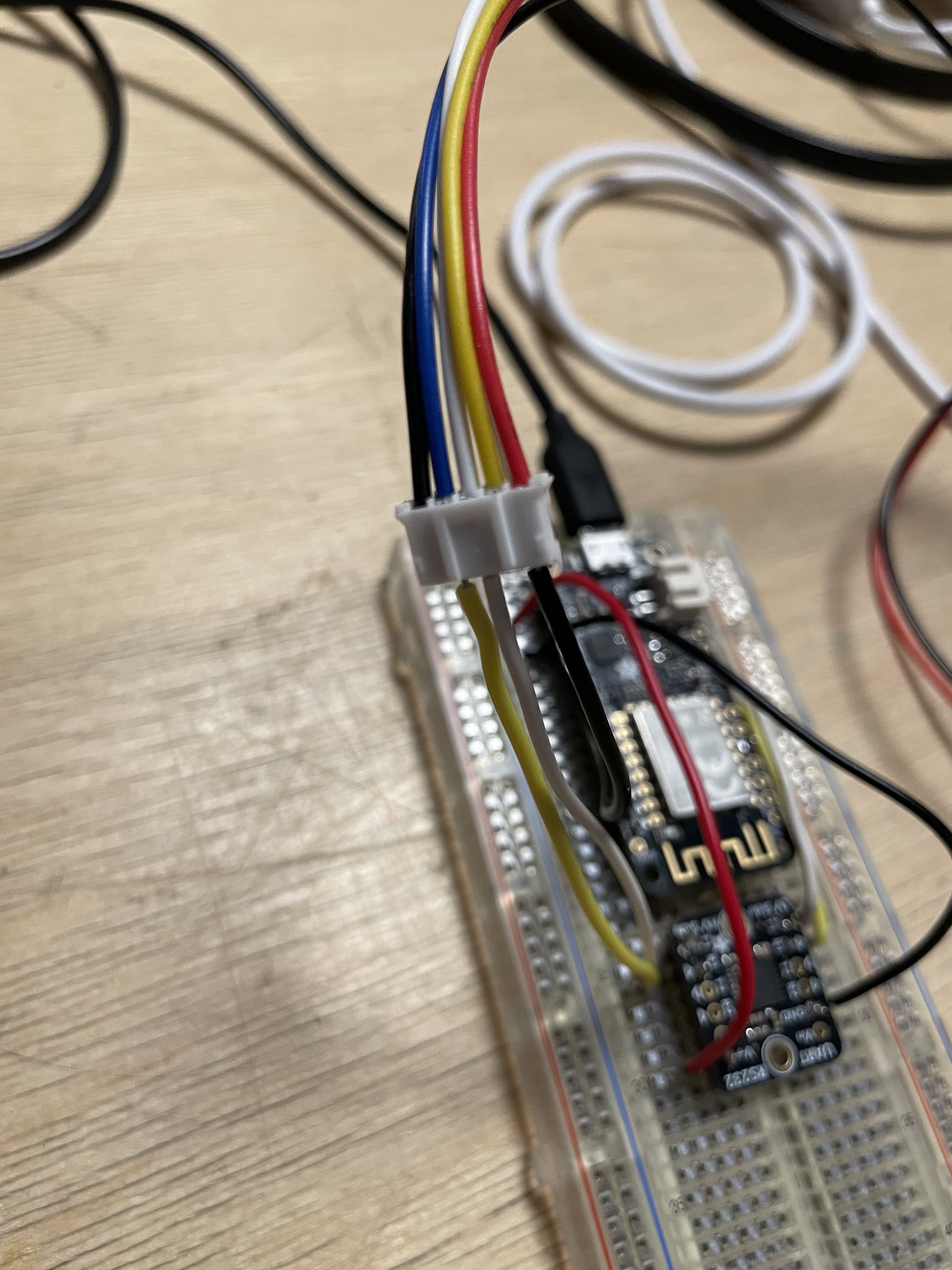
The adapter is connected directly to the printer. Here's a photo of my set-up if that helps. Im not sure where else I would measure.