Noob question here.
I'm planning on using a DEMUX and shift register to expand I/O pins for LED's
When using a DEMUX, let's say output 3 is enabled by the control pins 0011. Are the remaining outputs considered floating or are they pulled down internally? I haven't been able to find this information anywhere.
Wrong chip for that. Use TPIC6C595 (100ma outputs) or TPIC6B595 (150mA outputs).
3 IO pins on Arduino to control 8, 16, 24, 32 IO with daisy chained parts.
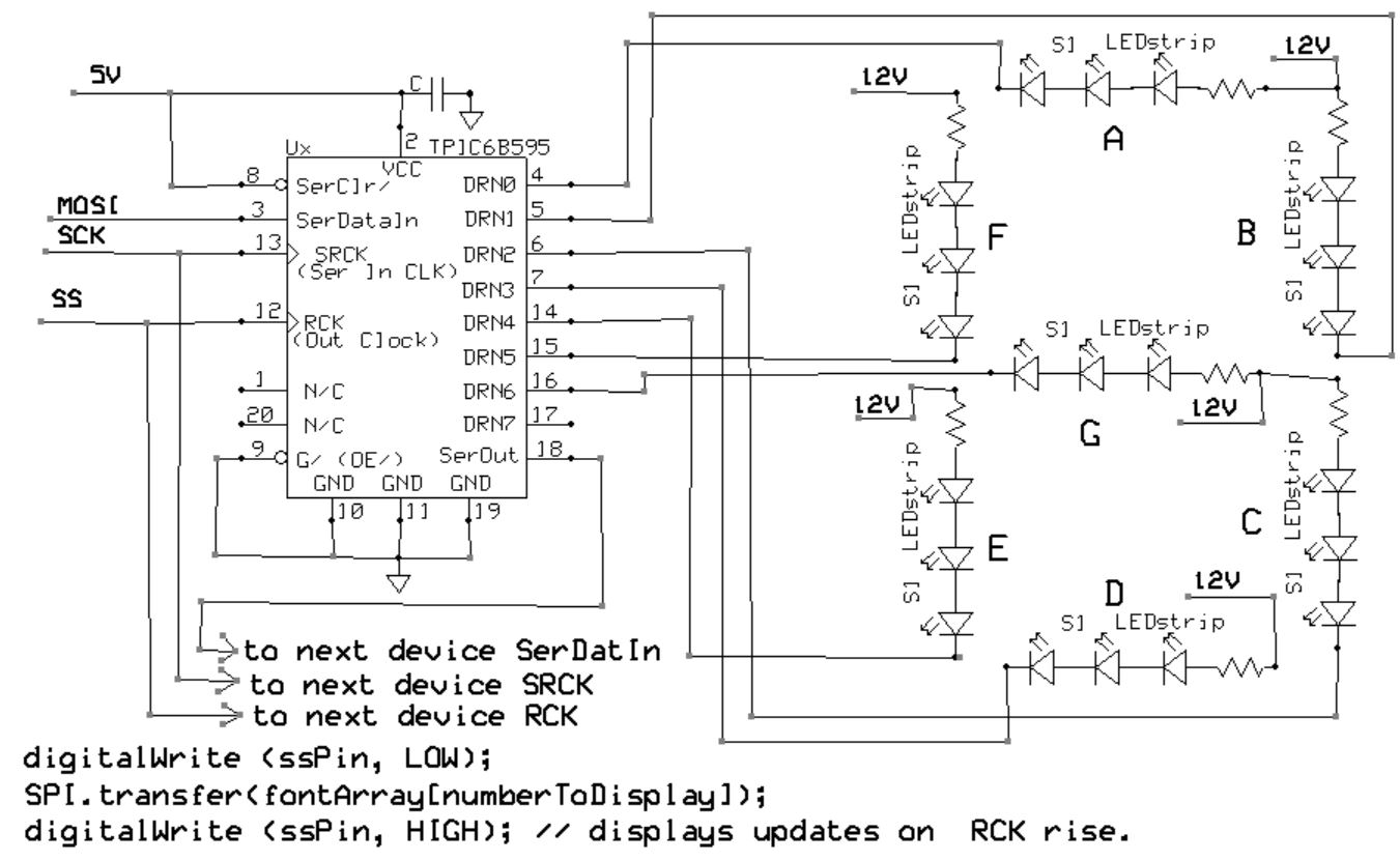
Set up LEDs as common anode parts, with outputs connected to cathode & current limit resistors.
Shift in a 1, output goes low, turns on LED.
Shift in a 0, open drain output goes, well open drain, and LED turns off.
digitalWrite (ssPin, LOW);
SPI.transfer(yourData);
digitalWrite (ssPin, HIGH); // output update on this rising edge
CrossRoads:
Wrong chip for that. Use TPIC6C595 (100ma outputs) or TPIC6B595 (150mA outputs).
3 IO pins on Arduino to control 8, 16, 24, 32 IO with daisy chained parts.
I plan on using the demux to switch transistors to drive the led's so the current rating is not important. I'll be using the shift register to control the address pins on the demux to switch on and off specific led's to create patterns.
An analog switch can be used to control just one device at a time. The other switched lines are by definition, not connected to anything and are thus floating. You can if you wish provide some weak pull-up or pull-down to each of these in order to set a default state to which they will revert whenever they are not selected while a BJT will simply have no base drive and be switched off.
I very much doubt that is what you want if you intend to light more than one LED at any one time.
If you want to set patterns, then as CrossRoads explains (or I would have had he not answered first) then you need one or more registers to store the pattern, bit by bit.
The TPIC6B595 is suggested as it is an 8-bit register which can be loaded by clocking in bits serially, can be chained to many devices to register multiple groups of 8 bits, and also includes FET drivers which can directly drive up to 150 mA each for LEDs.
Paul__B:
An analog switch can be used to control just one device at a time. The other switched lines are by definition, not connected to anything and are thus floating. You can if you wish provide some weak pull-up or pull-down to each of these in order to set a default state to which they will revert whenever they are not selected while a BJT will simply have no base drive and be switched off.
Thanks that what i was looking for.
Paul__B:
I very much doubt that is what you want if you intend to light more than one LED at any one time.
I plan on lighting 1 LED at a time, but switching at a frequency above what we can see so it appears as if multiple is on.
This is useful where you are constrained by the displays being already connected with both common anodes and common cathodes. The limitation is that since each LED is only on part of the time, you consequently have less brightness.
If your LEDs are separate or with only a common anode, there is no need to consider multiplexing for which you need very carefully crafted code; using the TPIC6B595s as described allows you to simply set each LED as desired and leave it until you need to change the pattern.
Bit of an "XY Problem" here, perhaps you should explain just what it is you want to do.
I plan on lighting 1 LED at a time, but switching at a frequency above what we can see so it appears as if multiple is on.
A common beginner’s mistake. All the disadvantages of using multiplexing with no advantage. Use the right chip and save yourself a ton of CPU cycles. Only some one very inexperienced would think of doing things like you plan.