Hi, I have a problem that I haven’t found an answer to in this forum:
I’m trying to read an input voltage that changes between 0.66v and -2.5v. I’ve tried around with voltage dividers and op-amp circuits like this one posted by robertnc in How to Read voltage +/- - #12 by 2112 :
My problem is that I can’t have the circuit change the voltage at the input. that is because I’m tapping into the circuit of an old analog electric piano to read notes being played and if the opamp circuit sends any voltage back into that it will change the sound. The other thing is that the piano has 76 keys and I want to read each one individually so I can’t use any components that are too expensive.
Since i want to convert the voltage to midi velocity I can afford losing some resolution. 1023 will be mapped to 255 anyways.
The way it works is that the voltage of each key sits at 0.66v and depending on how hard you press the key, the voltage goes down and slowly up again as long as you hold the key.
Does anyone know if what I’m trying to do is even possible? I’m thankful for every hint
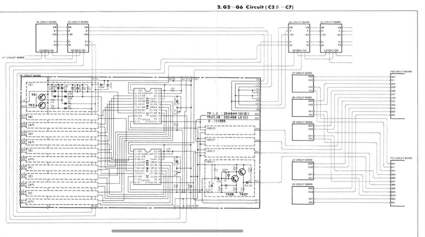
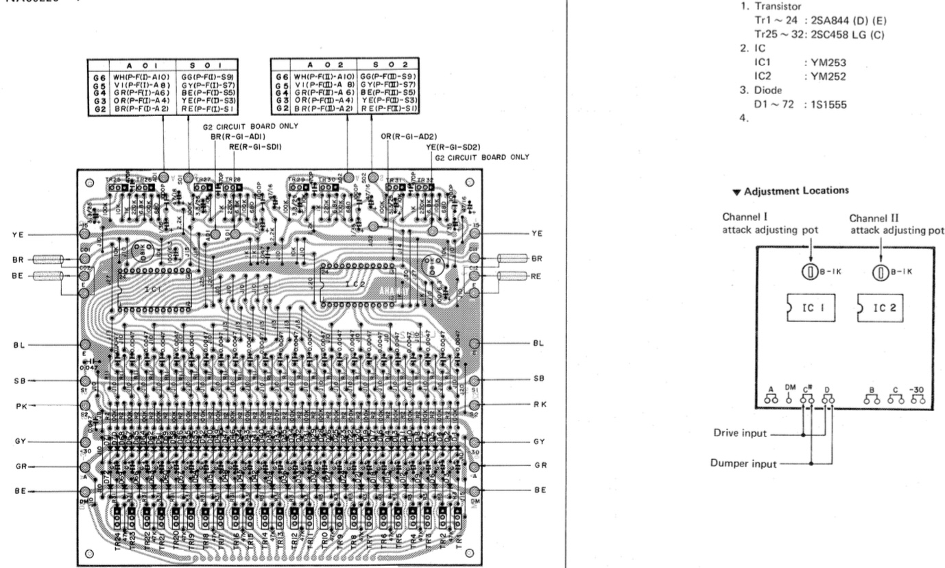
This is the circuit of the keyboard module that I am trying to read from. But it is one of many modules.
What I mean by the quote is that any opamp circuit I made always increased the voltage at the input so it fed some additional voltage back into the keyboard. I don’t want that because it will change the sound and the midi capability should only be in addition to the current functionality of the keyboard which I don’t want to compromise.
Unfortunately I can’t really show you a circuit because that’s what I am trying to develope and I have nothing working yet
The point where I’m tapping into is right before the IC chips
You can use an op to measure that signal but it will need to be supplied with +-12V (depending on the Op amp) Configure it in unity gain (output connected to -). Then connect the + to a 100K resistor and connect the other end of the resistor to your signal. You will now have a duplicate signal you can put resistor etc on and it will not effect the input signal. The output of the Op amp is connected replaces Input, I am not sure this will be doable for you.
That means buffering every signal with an opamp (unity gain circuit).
The opamps need a positive 5volt supply and a negative 5volt supply.
Signal to + input, opamp output connected to negative input.
The same key voltage is now available, buffered, at the opamp's output.
The voltage divider should be made with two resistors, not three.
One from opamp output to pin, and one between VCC and pin. In a 1:2 ratio respectively.
I would play with Aref voltages, to get A/D count up, but that would be the next step.
Another problem would be the multiplexers.
Leo..
Op means he cannot have a significant load on the piano output as that influences the piano.
So the resistor scheme does not work for him.
He also does not want 73 opamps to decouple the piano output...
Thank you everyone for the help, I’m going to order some of those LM324 amps. Would it also work to supply them with +/-15v from the piano? Because that is what I have around as supply pins on the circuit.
It’s the same project but I thought this was more general electronics related so I posted it here. Should I have asked my question there? If so I’m sorry, I’m very unexpierienced writing in forums
Also pretty new to electronics
What do you need from the key press signal to get the velocity? Only the time between the key press starts and ends? And do you want to get it into an Arduino pin?
(Focusing first in just one key)
In that case, you could use a comparator. When the voltage goes below 0.3V the output would be high (5v) and when it goes back above 0.3V it would be low (0V). So a square wave with the duration of the key press, that you would send to an Arduino pin.
The comparator has high input impedance, so it shouldn't influence the signal. But maybe you would need to clamp the signal, buffer...
If you need also the shape of key press signal, then you should do more things. But how do you want to manage this signal afterwards? In Arduino? analogically?
The voltage drops further the harder the key is pressed. So I want to monitor the relative voltage of each key via multiplexing and process it in software.
This would bias the signal between 0.5V and 2.5V, approximately. You should experiment and improve it with different variants. R3 maybe could be a capacitor.
Then, about multiplexing it (in the left/input side?), polling and sampling all in Arduino, I'm not sure.
I fear what you want to do cannot be done without a scope. You must axactly know what kind of signals you get. E.g. in this case it could be a pulse of different length. A DMM is not suitable for measuring dynamical signals.
Another possibility I’ve been thinking about is reading the switches directly under the keys digitally and processing it all in software. It’s a time based thing where the time between disconnecting from one contact and connecting to the other contact determines the velocity. I suppose it would be easier electronically though I would need 2 I/O inputs for each key =152. Though I don’t have enough experience to know if any of these 2 options is going to be too much to handle for the arduino. I’m a little worried about latency
I guess I’m going to do the op amp thing and if that doesn’t work I’ll see what I’ll do. I already learned so much researching for this project but my understanding of electronics is still on a pretty basic level. Maybe I can tackle the kind of stuff you need a scope for in the future as well
Hi,
Question, what happens when more than one key at a time is pressed, how will you measure each individual key?
Controller can only do one thing at a time.
You may need a faster processor to multiplex the inputs you are reading.
How many keys?
As you are looking at a time and amplitude dependent waveform of the keys, I highly suggest you use a scope.