I bought a transistor, a diode, a voltage controller and a 9 volt battery
I used a diode between the emitter of the transistor and changed the output to the 8 pin and connected it to other end of diode.
I basically hooked up the voltage controller so I can get 5 volts to run my motor, the output of the voltage controller goes to the motor, the negative part of the motor goes to the transistor collector, and the emitter goes to the common ground.
and my project is still not working
Is it because I am using the wrong specs for transistor?
specs are power dissipation = 75w
collector emitter voltage = 60v
collector base voltage = 70v
emitter base voltage = 5v
collector current = 10 A
You are wiring it up wrong. Wire it up like in the link.
Emitter to ground, base to a resitor and then on to an arduino output. Motor to collector, other end to 5V. Diode across the motor, cathode to +.
Remember to make the arduino pin an output in your sketch.
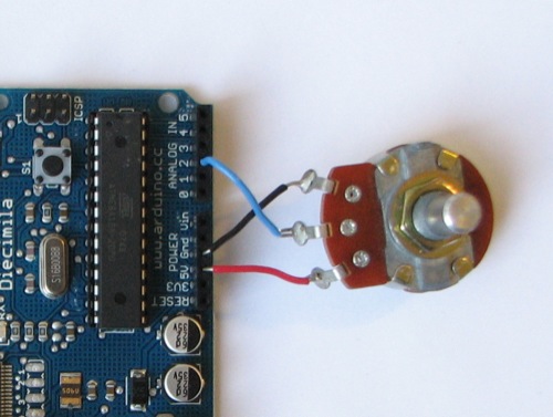
It is very hard to see everything but there are many things wrong.
When posting code select it and then hit the # icon.
The diode is the wrong way round, you have probably by now blown this up now.
You have no capacitors on the input and output of your regulator.
You are using pin 8 to produce a PWM output. PWM does not work on pin 8, look at the board and you might see (depending on the board) a ~ symbol in front of a pin number. This means it is capable of PWM. On the Uno this is pins 3, 5, 6, 10 & 11.
You are using a small 9V battery, these have very little capacity and don't last very long.