That should be o.k. but if it's just a 12V DC pump most of us would use low-side switching with just a single N-channel logic level MOSFET (the first schematic on that Nick Gammon page).
TomGeorge:
Hi,
Does the Arduino controller share the same gnd as the 12V supply for the pump?
If they can't you may have to use an opto-coupler as well.
Tom...
Hello Tom!
I'm using battery to power my arduino and I only use the mosfet to cut the 12v wire...
Bad news:
I have already fried 2 Mosfets.....
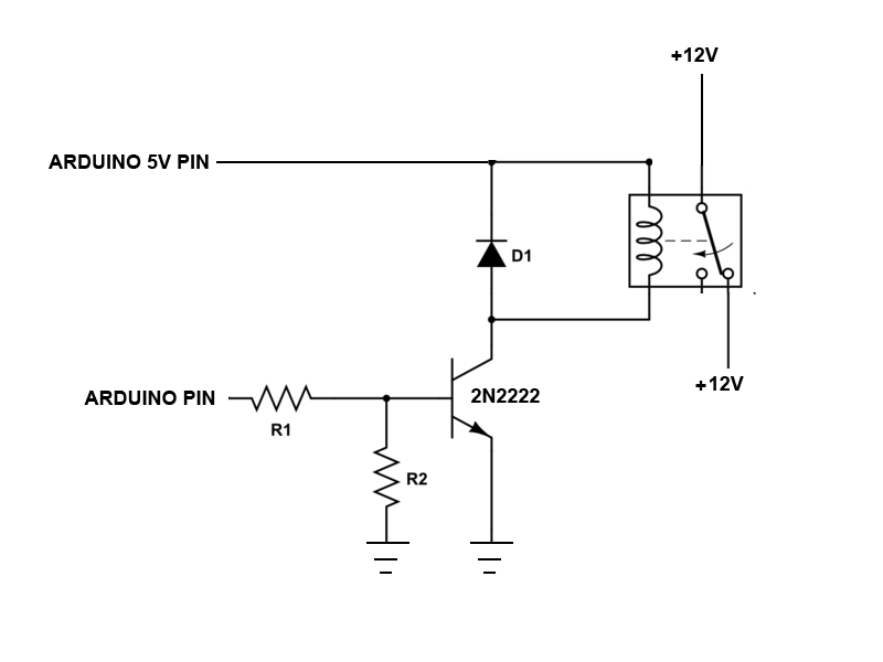
This is the schematic that fried my mosfet.... any idea?
Good news:
I got an opto-coupler now... haha...Will give it a try. But before that, can let me know if this is correct?? and where should i ground the opto-coupler? +12v ground? or can share the same ground as arduino???
Hi,
Can you post a picture of your project so we can see your component layout?
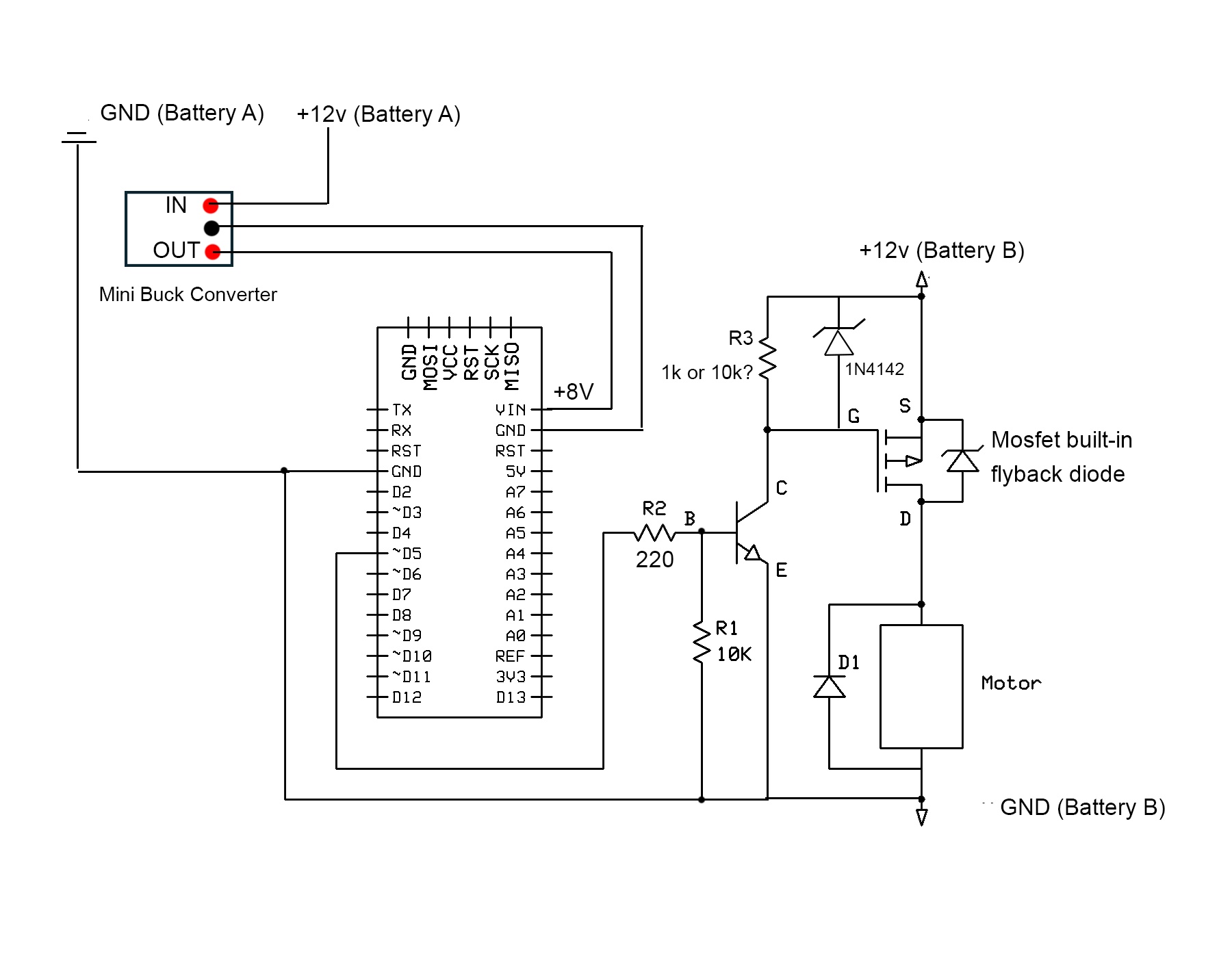
This is a better schematic, pointing out the connection required between gnd of Arduino and motor supply.
If you want to reduce the chance of frying your MOSFETs add a zener between gate and source.
Over voltage on the gate will always instantly destroy MOSFETs, you have to ensure this never
happens, either when handling the device, or in circuit, and a 12V zener is a great way to do this.
You still need a resistor between gate and source to turn the device off.
If the grounds were not commoned that would explain why you were destroying the MOSFETs - one circuit
attached to the gate, the other to the source, its a tug of war...
After more research, I think my previous schematic has a problem... For P-channel Mosfet, it should always pull-up right? If yes, do i still need to have the pull-down at transistor base? will it cause "floating" issue??
Hi,
You don't need the 10K at the base of the BJT, is low impedance and won't float like a MOSFET gate will.
You can leave it in, 10K will not be a problem.
The 10K between the gate and source of the P-CH MOSFET is essential.
With P-CH MOSFET the gate has to go NEGATIVE with respect to the Source to make it conduct, that is what the transistor does to the MOSFET gate.
Do you have to switch the positive of the motor, that is High Side switch?
It would be easier and lower component count if you switched the gnd side, or LOW SIDE switch with N-CH MOSFET.
TomGeorge:
Hi,
You don't need the 10K at the base of the BJT, is low impedance and won't float like a MOSFET gate will.
You can leave it in, 10K will not be a problem.
The 10K between the gate and source of the P-CH MOSFET is essential.
With P-CH MOSFET the gate has to go NEGATIVE with respect to the Source to make it conduct, that is what the transistor does to the MOSFET gate.
Do you have to switch the positive of the motor, that is High Side switch?
It would be easier and lower component count if you switched the gnd side, or LOW SIDE switch with N-CH MOSFET.
Haven't you tried the circuit yet?
Tom...
Hi Tom
Ah...Ok understand. I haven't test the new circuit. Just want to make sure the new circuit is safe before I test as I only left 1 or 2 P-channel mosfet...