The project is an illuminated wireframe sculpture display.
I am planning an installation of several thousand 3V LED seed pixels (0603, 1.6cm pitch, several tens of meters) on a bipolarity 2-wire string. Because of power considerations, I am thinking of splitting the long LED string into segments plugged into daisy-chained amplifier modules - the LEDs of each polarity all need to be synced, receiving the same signal. I would like to ask for advice on designing the amplifier PCBs.
[Bipolarity strings meaning: LEDs on 2-wire strings with alternating polarity. The polarity is switched at several KHz so that both polarities of LEDs can be lit. Further, each direction is a PWM signal which is frequently varied in order to generate patterns of varying brightness on the LEDs. Controllers are cheaply available commercially, although I am working on my own version using a WiFi-capable ESP8266 MCU]
Each amplifier takes the incoming signal, amplifies it and splits the output it between an attached LED string segment and downstream to the next amplifier. For the amplifiers, I am thinking of using an H-Bridge like the DRV8876. which seems to have enough power and fast enough switching. I am thinking of using DC 5V power, relying on PWM to keep the LEDs from frying.
Does this setup sound feasible? Is there any advice for signal conditioning, splitting the H-Bridge output, etc.? TIA!
This sounds iffy without current control. A block diagram would help.
What is your total current consumption and wire length needed? Are you sure that your LED can take a reverse bias of -5V?
Topic moved !! Please do not post in showcase and then proceed to ask for help, so I have moved it to the correct place for asking for help.
You might want to look at this How to get the best out of this forum before you proceed any further.
We only know what you tell us, and without knowing what you have, we don't stand a chance.
The alternating LED string is a very popular product, and I have tested these strings using my own bipolarity PWM (H-Bridge based) controller driving at 5V.
Every 0603 LED (which is what these strings use) I have seen has a reverse voltage of at least 5V. And since the LEDs are alternating, the vast bulk of the current will be through the LEDs in the forward direction. PWM is a maximum of 50% in either direction.
I see this mentioned all the time, since I first starting doing LED projects 3 years ago. Practically, the current seems to be determined by the voltage applied, which is why 'current-limiting resistors' are used to lower voltage to the recommended forward voltage if required.
You are welcome to convince me why my eyes are wrong.
Of course it is. That is a basic law of physics. However, driving a 2V LED with a 5V source will nearly instantly destroy the LED due to excessive current and heat generation, IF the source is capable of meeting the current demand.
That is why people use a resistor or constant current circuit to limit the LED current to safe values.
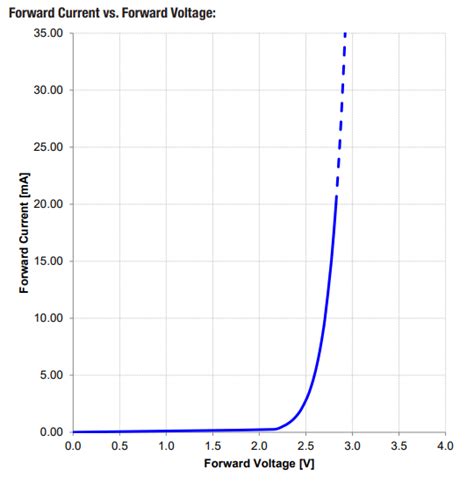
So nothing until you reach the turn on voltage of the LED, which depends on the colour of the LED, then it shoots rapidly upwards. A resistor is the simplest way to limit the current, by approximating a constant current circuit. This sort of effect only kicks in when the resistor is more than about 80Ω.
Using PWM Is not going to save them in any way.
Your eyes follow a similar logarithmic sensitivity curve, that is they are not very sensitive to absolute values. So if you over drive your LEDs they will slowly fail, along with the device which is supplying more current than it should.
You can measure this drop in light output with specialist equipment after about a week of them being on. This light drop can be used estimate the half life of the LED. That is where the light output drops to a half. Your eyes will probably not be able to spot this, because they are not as good as you think they are.
If you are not convinced then why do you think that they have such specialist equipment to measure the half life of an LED?
Conclusion :- All LEDs need something to limit the current, the simplest being a resistor.
I finally put a scope on the commercial driver, and found it was outputting 3v with a PWM of around 8hz (much slower than the recommendations I had googled up). So I'll be doing some reprogramming.
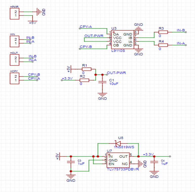
Meanwhile, I implemented the repeater module using the L9110S. 5V for connecting the modules then dropped down inside the module to 3.3V for the L9110S supply using an LDO with which I was already familiar.
(R1/R2 resistors are for statically selecting the supply voltage, R3/R4 are an attempt at providing for signal conditioning if necessary).
Seems to work like a charm.
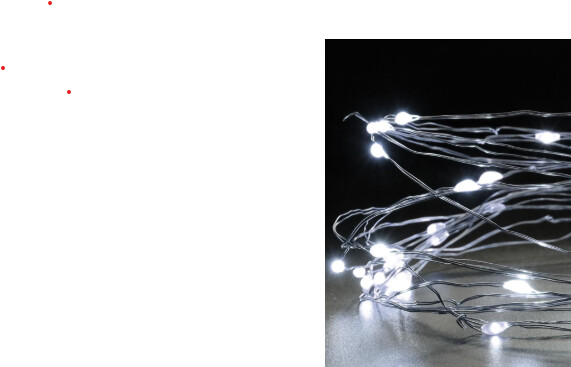
Below is the type of LED string (mine are same but with 1.6cm pitch, about $0.40 a meter - custom order). LED blobs are about 2mm wide (0603 chips). Maybe there is a resistor in there somewhere.