Hi everyone, I am working on a pretty basic project where a retro reflective sensor will operate a stepper motor a number of steps once the sensor becomes active, the reflector will be moving past the sensor. I have a sensor but not sure if it can be connected to achieve this as it allows 18v into the arduino. Question is, can this sensor be wired to work? or do i need to buy an "open collector NPN Sensor"? Cheers
Sensor i have is Baumer O200.GP-GW1J.72CV.
(https://www.baumer.com/medias/__secure__/Baumer_O200.GP-GW1J.72CV_EN_20240215_DS.pdf?mediaPK=9139686178846)
Generally speaking, even if I have never used that sensor, I think the answer is yes, it can be wired to Arduino. But a few questions for you.
First, why you choosed this sensor, I mean, what is your goal and application?
Second, the power required to run the sensor has nothing to do with the communication wire (aka no "18V into the Arduino").
Third, if it is a IO-Link communication (as far as I can see, it's, let's say, a "serial" interface with specific levels and protocol) you need is to know that protocol and physical characteristics and know how to handle it.
Even if you said you already have that sensor in your hands, I'm asking you all this because I can understand the fact that this sensor is very good and for professional usage (besides, it's not cheap, around 150 bucks, if I'm not wrong...) but can't be directly used with Arduino because its output isn't standard TTL serial, so maybe you could consider other retro reflective sensors that are easier to be interfaced to Arduino.
Just my curiosity...
@bmac1507
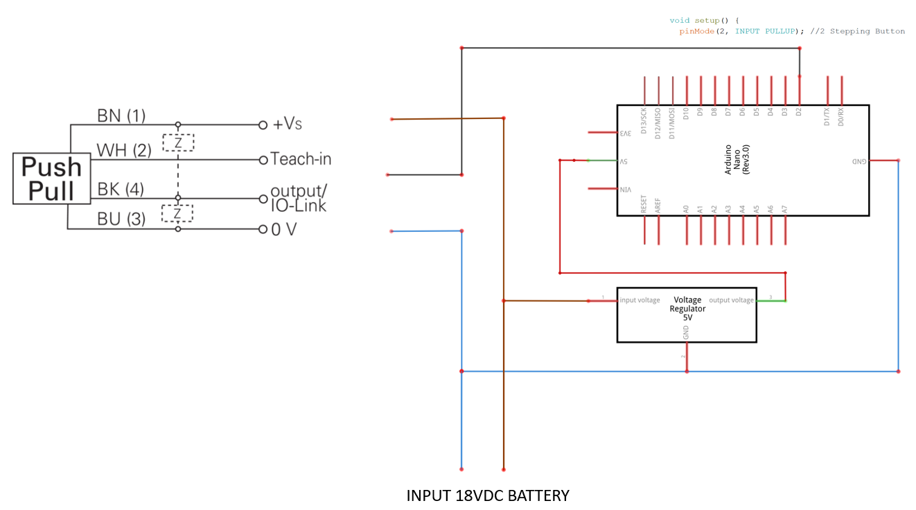
This should work:

Great approach!
Hi Faraday, thanks for your reply.
The application of this project will be used in a machining application, the stepper motor will power a machining slide and will be set up on a rotary table. So every time the table rotates 1 lap, the sensor will activate and advance the machining slide a small amount.
The reason i have this sensor is that I'm very new to this and ended up being sold one that isn't really suited. I'm happy to purchase a new one, but just want to make sure i get the correct one this time. After a bit of research, i have found another sensor from Baumer and added it into the sketch.
Really all I'm after, is a basic sensor to give a signal every rotation.
Do you think this sensor is suited and have I wired it correctly?
appreciate your help. Cheers
https://www.baumer.com/medias/secure/Baumer_O200.RR-NV1Z.72CV_EN_20240215_DS.pdf?mediaPK=9139682115614

Thanks for your time Jim, I will wire the sensor that i have up as you suggested with the 2N7002.
looks like an easy fix. Just for my learnings, which sensor should I have brought and how would i wire it to the Arduino?
How fast does it rotate?
The speed would vary from 5-20rpm
Without seeing your machining set-up I don’t know if either one is suitable but as far as connecting to the Arduino, the one with the NPN output would make more sense.
Note that the 2N7002 will invert the signal from the sensor but the data sheet does not specify if it high or low
Thanks Jim. Appreciate your help.
Will let you know how I go.
Sorry but I still can't imagine what machine you're talking about and where/how you intend to use it.
Anyway, if you just need to detect an axis rotation, why are you considering that specific and uncommon sensor (i.e. I haven't found any article or post about connecting and using it with Arduino) instead of one of the many common solutions like using a standard IR sensor (you just need a thin black line on the axis to mark and count rotations), just to start with the the first and probably most used solution? Are there constraints I'm not aware of?
PS: if the device you wish to control is somehow used in industrial environment, you better check local regulations regarding safety and modifications....
PS2: I'm not "Faraday", it's just a label the forum assigned to my account. My alias is "docdoc"... ![]()
Hi docdoc, Hope the attached sketch clears up what I need to achieve. The reason I chose this type of sensor I have is that I've seen the retro-reflector used in similar applications. This will be a one-off job and not a permanent setup. Happy to go with the standard IR sensor if I can't get the sensor I have to work. Thanks for all the advice.

Just curious, how is the stepper powered/driven?
Hi dougp, the stepper is powered by an 18v Makita Battery and a DRV8825 Driver.
The stepper has a 5:1 planetary gearbox and also geared down with Pullys and belt, the slide is only required to move 0.25mm every revolution.
Yeah, it helps but not so much, but it's my fault. ![]() I know I'm not an expert on tooling machineries, so I can't get exactly how that tool works, what is the "component to be machined", and where the left picture item is placed on the second one, and so on.
I know I'm not an expert on tooling machineries, so I can't get exactly how that tool works, what is the "component to be machined", and where the left picture item is placed on the second one, and so on.
Anyway, forgive me for my (dumb?) questions that came out of my mind watching that image:
- what is the size of the left picture item?
- what the distance between the sensor and the reflector?
- what is the size of the inner space between the red cylinder and the component?
- why are you planning to have an Arduino (and its battery) on a rotary table and a stationary marker instead of a stationary sensor and a rotating marker?
- what that line between Arduino and the top tool means? Does it need to control something?
- what is the airspeed velocity of an unladen swallow?
PS: ok, forget the last one, I'm just kidding ![]() it's the Monty Python's Holy Grail movie (know?) quote coming out to me when asking many "what" questions...
it's the Monty Python's Holy Grail movie (know?) quote coming out to me when asking many "what" questions... ![]()
Hope this helps a bit more,
The Component being machined is set up on stands and doesn't rotate.
The Rotary table, Green support stand, Slide, Tooling, Arduino, Battery and Sensor all rotate together.
The Right picture is an enlarged pic from the centre of the Left picture.
Answer to your questions below.
- what is the size of the left picture item?
The Rotary Table is 2200mm dia - what the distance between the sensor and the reflector?
Aim to mount sensor approx 100mm away. Can adjust this from 50mm to 300mm - what is the size of the inner space between the red cylinder and the component?
The Red part is the surface which will be machined. - why are you planning to have an Arduino (and its battery) on a rotary table and a stationary marker instead of a stationary sensor and a rotating marker?
Arduino (and its battery) will be connecteds to stepper and slide and all rotating - what that line between Arduino and the top tool means? Does it need to control something?
Cable connecting Arduino/Battery to stepper Motor
Thanks, I think I now have a better view of the whole thing (starting from the fact I didn't realize that the image on the right was an enlargement of the left one...).
However, I made a typo on my question #1. 3 I used "red cylinder" instead of "green cylinder" (there's no "red cylinder" ![]() ), but it's ok, it wasn't a critical question anyway.
), but it's ok, it wasn't a critical question anyway.
Standard proximity IR sensors (like the ones used for obstacle detection) range is from 10 up to 60-70 mm so they can't be effectively used here.
But there are many others around on the market, less common but with a distance detection range similar to your one. Like Sharp GP2Y0A41SK0F I read it goes from 40 to 300 mm so I think you could get one and make some tests with it. If those brown legs are part of the machine, you could get a trigger signal from the sensor for each of them, so if you know you have four legs, to count the rotations you just need to divide by 4.
BTW, why you marked your post#15 as a "solution"?
PS: It's just my curiosity, but I still can't get what is the "component to be machined" depicted on the first drawing, it looks more like a stand or base where an object will be put, and I have no idea of what that tool is made/used for (even if I googled around a bit), the whole looks kinda lathe but it isn't. So, it's not really important but as I'm still curious, if you have a photo of the real machine (or a link where it is described, or its name) it'd help me better understand what we're talking about.
This topic was automatically closed 180 days after the last reply. New replies are no longer allowed.