One can find these almost anywhere on the 'net. Has anyone an opinion on whether one is decidedly better - in terms of the output signals - than another?
I ask because I have one that gives a funky signal compared to one which does not. More precisely, the funky one misses the first detent going in the opposite direction to what it was, then it's fine. Reverse direction again and it misses the first detent.
This encoder is on a breakout board that came with my kit.
The good one was bought as a standalone item and, sadly, is no longer available from Amazon.
I have used many of these encoders both on Arduino's and Raspberry Pi and also Pico 2040.
I have found that there is often a small blip when changing direction, but with the right sort of decoding software it is not a problem.
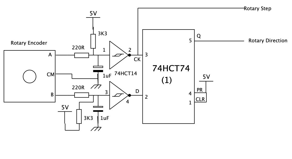
I do not know what sort of decoding your library uses, but I do know there is a lot of rubbish methods in a lot of Arduino libraries. The only method you should use is that one that involves a state machine. The one I use is Rotary Library from Encoder Library, for Measuring Quadarature Encoded Position or Rotation Signals because that one is implemented correctly.
When I am on platforms other than an Arduino, or I need more encoders tha just one, I normally write my own state machine routine. This is the state diagram:-
This one will do that occasionally but the reversing thing is consistent. It will also jitter a bit on one channel with just a little bit of torque in one or the other direction, not enough to actually turn but enough that you can feel it's not resting at the detent bottom.
The one with built-in pullups is the problem – the only time it works is when the on-board pullups are enabled (by tying encoder V+ to Vcc). Processor pullups – pinMode(X, INPUT_PULLUP) appear irrelevant to this encoder.
I would say that is what I would expect to happen. The internal pull up resistors are quite weak with a range of values between 33K and 50K. If you then go and put a floating 1K resistor in parallel with it then I would expect the internal pull up resistors to have no effect.