RS485 Communication with Grundfos Genibus

It seems like a good starting point would be to confirm exactly what the serial parameters are - baud rate, parity etc. As, without knowing these, any attempt to communicate with the device will be a shot in the dark.

The "written data" looks like it matches the message format in post #4.

Another useful piece of information is that the device has the address 0xE7. Presumably as the controller, the software has given itself the address 0x00.

If you can figure out the serial comms parameters, then there's a good chance that you will be able to talk to the device.

ok so im still going around in a circles here unfortunately.

wrt to the CRC. does that need to be calculated on the nano as i read somewhere that they are stored in the eeprom?
so if i simply send the crc byte will it not work?

I have extracted code that i found in the github genibus code as below: (they state that this is for datalink.ino/


static uint8 sendBuffer[0xff];
static Crc crc(0xffffu);

static const uint8 connectReqPayload[] = {
  0x00, 0x02, 0x02, 0x03, 0x04, 0x02, 0x2e, 0x2f, 0x02, 0x02, 0x94, 0x95
};

void dumpPDU(byte len)
{
  uint8 idx;

  for (idx = 0; idx < (len + 6); ++idx) {
     //printf("%#x ", sendBuffer[idx]);   
     sendBuffer[idx];
  }
}

void connectRequest(uint8 sa)
{
   sendPDU(0x27, 0xfe, sa, connectReqPayload, ARRAY_SIZE(connectReqPayload)); 
}

void sendPDU(uint8 sd, uint8 da, uint8 sa, uint8 const * data, uint8 len)
{
  uint8 idx;
  uint16 calculatedCrc;

  sendBuffer[0] = sd;
  sendBuffer[1] = len + ((uint8)0x02);
  sendBuffer[2] = da;
  sendBuffer[3] = sa;
  
  for (idx = ((uint8)0x00); idx < len; ++idx) {
    sendBuffer[idx + ((uint8)0x04)] = data[idx];
  }

  crc.init(0xffff);
  for (idx = ((uint8)0x01); idx < (len + ((uint8)0x04)); ++idx) {
    crc.update(sendBuffer[idx]);
  }
  calculatedCrc = crc.get();
  sendBuffer[idx] = HIBYTE(calculatedCrc);
  sendBuffer[idx + 1] = LOBYTE(calculatedCrc);  
  
  for (idx = 0; idx < (len + ((uint8)0x06)); ++idx) {
     Serial.write(sendBuffer[idx]);
  }
}


the following is exmaple01.ino in the genibus library


#include <SPI.h>
//#include <Ethernet.h>
//#include <EthernetUdp.h>
#include <Genibus.h>
#include <Types.h>
#include <Pdu.h>
#include <Crc.h>

#define GB_MASTER_ADDRESS  0x01

//byte macAddress[] = { 0xde, 0xad, 0xaf, 0xfe, 0xaa, 0x55  };
//byte subnet[] = { 255, 255, 255, 0 };
//unsigned int localPort = 6734;

/* TODO: The IP-configuration has to be adjusted to your needs!!! */
//IPAddress ipAddress(192, 168, 100, 20);
//byte gateway[] = { 192, 168, 100, 1 };

#define LED_PIN  9  /* Pin 13 has an LED connected on most Arduino boards, otherwise this should be changed. */
                    /* Pin 9: led connected on Arduino Ethernet board*/

void writeByte(byte value)
{
  /* TODO: Write to UDP, LCD or an additional serial port. */  
}

void setup(void)
{
 
  pinMode(LED_PIN, OUTPUT);
  digitalWrite(LED_PIN, LOW);
  Serial.begin(9600);
 // Ethernet.begin(macAddress, ipAddress);
 
/*
** 'Udp.begin()' generates a strange
**   "As of Arduino 1.0, the Udp class in the Ethernet library has been renamed to EthernetClient."
** compiler error (This doesn't hold for Arduino examples).
*/
//  Udp.begin(localPort);
  
  delay(1000); 
}

typedef enum tagRcv_State {
    RCV_IDLE,
    RCV_COUNTING
} Rcv_State;

void loop(void)
{
  byte receivedByte;
  byte byteCount;
  byte idx;
  Rcv_State state = RCV_IDLE;
  Serial.print("RCV_IDLE: ");
  Serial.print(state);
  Serial.print("\n\r");
  
  connectRequest(GB_MASTER_ADDRESS);
  while (Serial.available() == 0) {
    /* Blocking for now. */
  }
  /* Well, it seems the pump is talking to us :-) */
  digitalWrite(LED_PIN, HIGH);

  idx = 0;
  while (Serial.available() > 0) {  /* We are not considering inter-byte delays -- reception may prematurely terminate !? */
    // delay(1);  /* But could a small delay lead to buffer overflows??? */
                  /* Bottom line: The 'real' receiver shall use SerialEvent()! */
    receivedByte = Serial.read();
    Serial.print("receivedByte: ");
  Serial.print(receivedByte);
  Serial.print("\n");
    if (idx == 1) { /* Length byte? */
      byteCount =  receivedByte + 2;
      state = RCV_COUNTING;
    }
Serial.print("RCV_COUNTING: ");
  Serial.print(state);
  Serial.print("\n\r");
    if (state == RCV_COUNTING) {
      	if (--byteCount == 0) {
		break; /* We're done. */
	}
    }
    ++idx;
    writeByte(receivedByte);
    
  }
    Serial.print("LED_PIN low ");
    Serial.print("\n\r");
    digitalWrite(LED_PIN, LOW);
    delay(2000);
}


am i perhaps sending the correct values but because the nano is not caculating the crc it is not working? :confused:

ok so i have now modified the code to work with hardwareserial and i am getting a different response as attached.

#include <Arduino.h>

// Uses PJRC AltSoftSerial library which is better than the standard SoftwareSerial library (IMHO)
// Get it here: https://www.pjrc.com/teensy/td_libs_AltSoftSerial.html
//
// All pin numbers are for an Arduino UNO.

#include <AltSoftSerial.h>

// MAX485 : RO to pin 8 & DI to pin 9 when using AltSoftSerial
#define RE 11
#define DE 12

// const byte msg1[] = {0x27, 0x0F, 0x20, 0x01,
//                      0x02, 0x04, 0x02, 0x10, 0x1A, 0x1B, 0x04, 0x02, 0x04, 0x05, 0x03, 0x81, 0x06,
//                      0x80, 0x2A, 0xAA };

// const byte msg1[] = {0x27, 0x0E, 0xFE, 0x01,
//                      0x00, 0x02, 0x02, 0x03, 0x04, 0x02, 0x2E, 0x2F, 0x02, 0x02, 0x94, 0x95,
//                      0x2A, 0xAA };

// const byte msg1[] = {0x27, 0x0E, 0xFE, 0x01,
//                      0x00, 0x02, 0x02, 0x03, 0x04, 0x02, 0x2E, 0x2F, 0x02, 0x02, 0x94, 0x95,
//                      0x2A};

// const byte msg1[] = {0x27, 0x0F,0x20,0x04,0x02,0x10,0x1A,0x1B,0x4,0x02,0x05,0x03,0x81,0x06,0x80,0x2A};

// const byte msg1[] = {0x27,0x0E, 0xFE, 
//                     0x01, 0x00, 0x02, 0x02, 0x03, 0x04, 0x02, 0x2E, 0x2F, 0x02 ,0x02, 0x94, 
//                     0x95, 0xA2, 0xAA};

// const byte msg1[] = {0x27,0x03, 0xe7, 
//                     0x02, 0x95,
//                     0x4E, 0xD6};

    // const byte msg1[] = {0x27, 0x2e, 0xe7, 0x00, 0x02, 0x15, 0xb4, 0xa5, 0xb3, 0xa7, 0xaa, 0xa6, 0xac, 0xa9, 0xb1, 0xa4,  
    // 0xad ,0xb0, 0xa3, 0xb2, 0xaf, 0xab, 0xa8, 0xb6, 0x51, 0xae, 0xb5, 0x0b, 0x13, 0x10, 0x02, 0x0f,  
    // 0x0d, 0x0c, 0x0e, 0x14, 0x12, 0x01, 0x13, 0x16, 0x09, 0x07, 0x0a, 0x6c, 0x08, 0x00, 0x15, 0x05,  
    // 0xcb, 0x6c};                                                         


// const byte msg1[] = {0x27, 0x07, 0xEF, 0x01,
//                      0x03, 0x81,0x00,0x06,0x92,0xD};


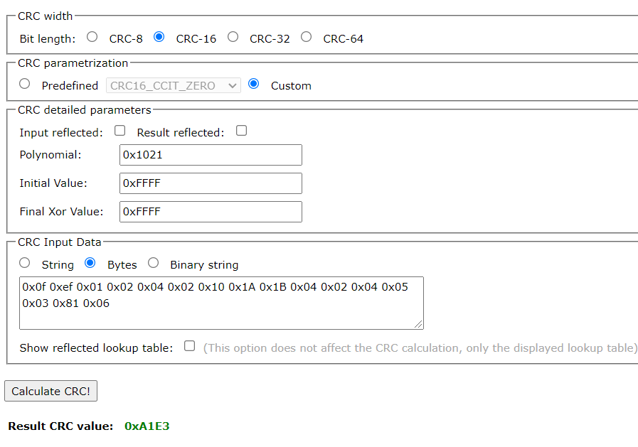
const byte msg1[] = {0x27,0x0f, 0xef, 0x01,
0x02, 0x04, 0x02, 0x10, 0x1A, 0x1B, 0x04, 0x02, 0x04, 0x05, 0x03, 0x81, 0x06,
0x92, 0xA4};


// byte values[11];
AltSoftSerial swSerial;

void setup() {
  Serial.begin(9600);

  // set this to the required baud rate - max of 19200 baud
  swSerial.begin(9600);
  pinMode(RE, OUTPUT);
  pinMode(DE, OUTPUT);

  // put RS-485 into receive mode
  digitalWrite(DE, LOW);
  digitalWrite(RE, LOW);

  // delay( 1000 );
}

void loop() {
  uint32_t startTime;
  uint8_t  rxByte;
  
  Serial.println("Sending command");
  Serial.print("Response: ");
  
  // put the MAX485 into transmit mode
  digitalWrite(RE, HIGH);
  digitalWrite(DE, HIGH);  

  // send the message
  Serial.write( msg1, sizeof(msg1) );
  // wait for all of the message to be sent
  Serial.flush();

  // put the MAX485 back into receive mode
  digitalWrite(RE, LOW);
  digitalWrite(DE, LOW);

  startTime = millis();
  // wait for up to 2 seconds for any reply and print out any received bytes
  while ( millis() - startTime < 2000UL ) {
    if ( Serial.available() ) {
      rxByte = Serial.read();
      Serial.print( rxByte, HEX );
      Serial.print( " " );
    }
  }
  Serial.println();
  Serial.println();

  // 5 second delay, then repeat the whole process again
  // delay( 5000 );   
}

it appears as though i am getting a response which does not include the start delimiter reply of 0x24.
the length and destination is correct as well as the source address

The CRC is definitely not stored in EEPROM. The CRC should be calculated on the fly for every message sent. Unless of course you are sending a fixed predefined message in which case you would know the CRC beforehand.

The code you posted in #23 looks like it is preparing a message to be transmitted. The sendPDU function does all the work of assembling the message and calculating the CRC. The message is then written to the hardware serial port.

I would try and track down the actual CRC library that they are using. I'm not a CRC guru so I don't know enough about the Ardiuno CRC library to know if you could use that instead. The documentation for that library suggests that you can set the polynominal, initial and final values.

Just spotted something which may be relevant. In your latest code, the pre-set message msg1 is talking to a destination address of 0xEF. The earlier successful messages were going to destination address 0xE7.

Also, I can't see anything in the code in #23 that is controlling the transceiver of the RS485 line driver. That may be because they were using an RS485 line driver with a built in switch-to-transmit capability. There have been a couple of cheap RS485 modules that didn't use RE & DE signals at all.

If the code you posted in #23 compiles, then you should be able to modify it to work with the RS485 module. In the sendPDU function, change the for loop at the end to something like:

  // put the MAX485 into transmit mode
  digitalWrite(RE, HIGH);
  digitalWrite(DE, HIGH);

  for (idx = 0; idx < (len + ((uint8)0x06)); ++idx) {
     swSerial.write(sendBuffer[idx]);
  }

  // put the MAX485 back into receive mode
  digitalWrite(RE, LOW);
  digitalWrite(DE, LOW);

Don't forget to define RE & DE and setup the software serial port in setup.

If you are trying to use the hardware serial port, then you need to include a serial.flush just before switching back to receive mode. And don't forget that the hardware serial port is also being used by the USB serial link back to your PC.

ok.
I managed to get the developer login to the software whereby i was then able to see all parameters and also dev debug the software and control the unit from software side.
i could then also view and filter the start/stop PDU communication between the software and the unit.
I also hooked up the pc tool usb-rs485 connector AS WELL as the arduino-max485 A & B line SIMALTANEOUSLY to the unit.

The end result is that i have now got the unit working and functioning as required.
A MASSIVE thanks to @markd833 for your assistance with this project. Your input and help was instrumental and I truly appreciate it a lot. Thank you.
My working code is as follow. (i will be tweaking it here and there, but it is working as desired for right now)

#include <Arduino.h>

#include <AltSoftSerial.h>

#define confirmOff_1         4      // D4    Wash Off
#define confirmWash          5      // D5    Wash On
#define confirmFill          6      // D6    Fill On
#define confirmOff_2         7      // D7    Fill Off

#define MASTER_RE           11      // Receive/Transmit Pin connected to RS485 Transmit Enable. Short Receive and Transmit. 1 for Transmit, 0 for Receive
#define MASTER_DE           12

const byte msgON[] = {0x27 , 0x05 , 0xE7 , 0x00 ,0x03 , 0x81 , 0x06 , 0xFF , 0x09};

const byte msgOFF[] = {0x27 , 0x05 , 0xE7 , 0x00 ,0x03 , 0x81 , 0x05 , 0xCF , 0x6A};

AltSoftSerial swSerial;


void openValve(){

uint32_t startTime;
  uint8_t  rxByte;
  
  Serial.println("Sending command");
  Serial.print("Response: ");
  
  // put the MAX485 into transmit mode
  digitalWrite(MASTER_RE, HIGH);
  digitalWrite(MASTER_DE, HIGH);  

  // send the message
  swSerial.write( msgON, sizeof(msgON) );
  // wait for all of the message to be sent
  swSerial.flushOutput();

  // put the MAX485 back into receive mode
  digitalWrite(MASTER_RE, LOW);
  digitalWrite(MASTER_DE, LOW);

  startTime = millis();
  // wait for up to 2 seconds for any reply and print out any received bytes
  while ( millis() - startTime < 2000UL ) {
    if ( swSerial.available() ) {
      rxByte = swSerial.read();
      Serial.print( rxByte, HEX );
      Serial.print( " " );
    }
  }
  Serial.println();
  Serial.println();


}

void closeValve(){

uint32_t startTime;
  uint8_t  rxByte;
  
  Serial.println("Sending command");
  Serial.print("Response: ");
  
  // put the MAX485 into transmit mode
  digitalWrite(MASTER_RE, HIGH);
  digitalWrite(MASTER_DE, HIGH);  

  // send the message
  swSerial.write( msgOFF, sizeof(msgOFF) );
  // wait for all of the message to be sent
  swSerial.flushOutput();

  // put the MAX485 back into receive mode
  digitalWrite(MASTER_RE, LOW);
  digitalWrite(MASTER_DE, LOW);

  startTime = millis();
  // wait for up to 2 seconds for any reply and print out any received bytes
  while ( millis() - startTime < 2000UL ) {
    if ( swSerial.available() ) {
      rxByte = swSerial.read();
      Serial.print( rxByte, HEX );
      Serial.print( " " );
    }
  }
  Serial.println();
  Serial.println();

}

void setup() {
  
  Serial.begin(9600);     
  swSerial.begin(9600);                // Baudrate of Serial Comms

  pinMode(confirmOff_1, INPUT_PULLUP);   
  pinMode(confirmOff_2, INPUT_PULLUP);
  pinMode(confirmWash,  INPUT_PULLUP);
  pinMode(confirmFill,  INPUT_PULLUP);
   
      
  pinMode(MASTER_RE, OUTPUT);  
  pinMode(MASTER_DE, OUTPUT);            // Declare Enable pin as output


  digitalWrite(MASTER_DE, HIGH); 
  digitalWrite(MASTER_RE, HIGH);          // Transmit Mode to send Data


}

void loop(){

  int washOff = digitalRead(confirmOff_1);
  int fillOff = digitalRead(confirmOff_2);
  int washOn  = digitalRead(confirmWash);
  int fillOn  = digitalRead(confirmFill);

    
      if(fillOff == HIGH){
        fillOn = LOW;
        Serial.println("Fill Off");
        closeValve();                 //function to be implemented that will send packet to GENI to close the water valve
        }
      if(washOff == HIGH){
          washOn = LOW;
          Serial.println("Wash Off");
          closeValve();               //function to be implemented that will send packet to GENI to close the water valve
        }
       if(washOn == HIGH){
          washOff = LOW;
          Serial.println("Wash On");
          openValve();              //function to be implemented that will send packet to GENI to open the water valve
        }
        if(fillOn == HIGH){
          fillOff = LOW;
          washOn = LOW;
          Serial.println("Fill On");
          openValve();              //function to be implemented that will send packet to GENI to open the water valve
        }
        Serial.println("        ");
        Serial.println("        ");
        // delay(4000);


}


1 Like

Hello,
sorry, I am a bit late to contribute. Just found this thread.
Can I ask you which developer login you meant. Is it from Grundfos? Which kind of software you are talking about? Are this windows executables or is it C code?
In case of interest, I have C code for CRC calculation for Genibus. The polynom is table based, so it is a bit lengthy.
Thank you.

hi there.
i required an arduino -> max485 solution to activate and deactivate a grundfos AQTap from microcontroller. The attached 'solution' code correctly works now with the product via the A-B rs485 pins on the unit.
it is written in C yes.
The software that i obtained is Grundfos own software and I had to get the development login for it from technical team in India.
I would be interested to see your CRC Genibus code if possible. :slight_smile:

1 Like

This topic was automatically closed 180 days after the last reply. New replies are no longer allowed.