Yes I could tell you which SMD resistors to move. And how to connect to the Due.
But first off, I would try all the examples for a SPI OLED. e.g. from Adafruit_SSD1306 and u8glib.
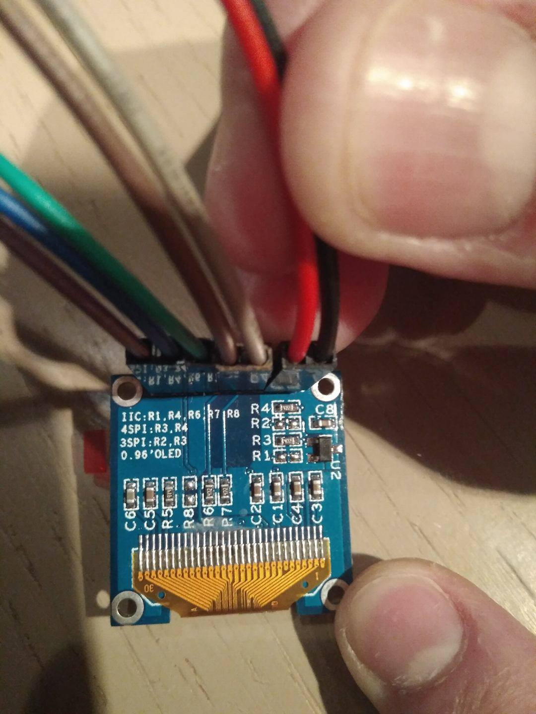
As I showed in #1, it is easy to select the constructor and pins for SPI.
You do not need to do any SMD soldering. You can see exactly what your OLED can do. You have a comfortable smug feeling when you see that your OLED hardware is working ok.
The default hardware SPI pins for your Due are on the 3x2 header. You can choose any GPIO pins for CS, DC, RST.
But you can also do everything in software SPI e.g.
//U8GLIB_SSD1306_128X64 u8g(13, 11, 10, 9); // SW SPI Com: SCK = 13, MOSI = 11, CS = 10, A0 = 9
As Oliver said in #5. the DO pin is SCK. The DI pin is MOSI. The example constructors don't seem to have a RST argument. But actually they accept an extra RST argument e.g.
//U8GLIB_SSD1306_128X64 u8g(13, 11, 10, 9, 8);	// SW SPI Com: SCK = 13, MOSI = 11, CS = 10, A0 = 9, RST  = 8
//i.e. using your pcb markings
//U8GLIB_SSD1306_128X64 u8g(13, 11, 10, 9, 8);	// SW SPI Com: DO = 13, DI = 11, CS = 10, DC = 9, RST  = 8
Personally, I find it very confusing when examples omit the RST argument.
Most Ebay boards have a RST pin. If you don't control it, your display does NOT work.
Adafruit boards mostly have a RST pin. They have an onboard pullup resistor. So if you do not connect the RST pin it is in a known state.
Adafruit examples are notorious for omitting the RST argument. But just like u8glib, Adafruit_SSD1306 accepts the extra RST argument in the constructor.
David.