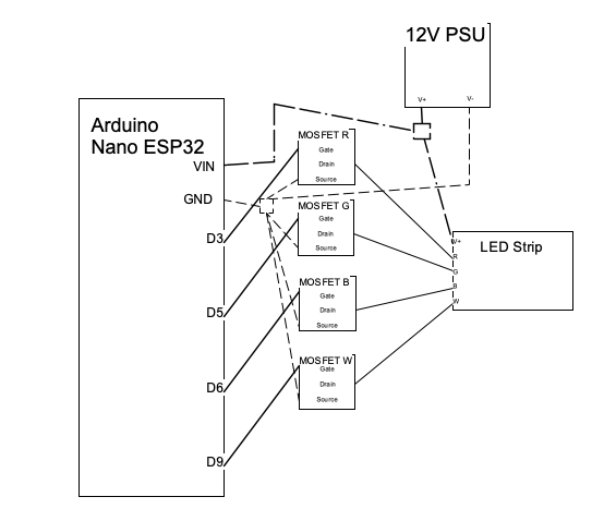
Hi, I am new to Arduino architecture. I've been trying for days to get my Nano ESP32 to run a simple analog RGBW strand from ETC Eos via sACN over Wifi. I've followed the instructions I've been able to find online for wiring and I tried to use ChatGPT and other sources to figure out the code. The WiFi portion seems to work. I can get the device to ping, but I can't get it to output anything to the tape. The code compiles just fine. I'll Copy/paste the code below, so if anyone can help me figure out what I'm doing wrong, that would be great.
#include <WiFi.h>
#include <ESPAsyncE131.h>

const char* ssid     = "NETGEAR";
const char* password = "";

// --- Universe settings ---
#define E131_UNIVERSE 1
#define CHANNEL_R 1
#define CHANNEL_G 2
#define CHANNEL_B 3
#define CHANNEL_W 4

// --- GPIO pins ---
#define PIN_R 6
#define PIN_G 8
#define PIN_B 7
#define PIN_W 18

// Onboard LED pin (Nano ESP32 built-in LED)
#define LED_PIN LED_BUILTIN

// --- E1.31 receiver ---
ESPAsyncE131 e131(1);

void blinkFast() {
  digitalWrite(LED_PIN, !digitalRead(LED_PIN));
  delay(100);
}

void blinkSlow() {
  digitalWrite(LED_PIN, !digitalRead(LED_PIN));
  delay(500);
}

void setup() {
  Serial.begin(115200);
  delay(2000);
  pinMode(LED_PIN, OUTPUT);

  Serial.println("Booting...");

  // --- PWM setup ---
  ledcAttachPin(PIN_R, 1);
  ledcAttachPin(PIN_G, 2);
  ledcAttachPin(PIN_B, 3);
  ledcAttachPin(PIN_W, 4);

  ledcSetup(1, 5000, 8);
  ledcSetup(2, 5000, 8);
  ledcSetup(3, 5000, 8);
  ledcSetup(4, 5000, 8);

  // --- WiFi connect ---
  Serial.print("Connecting to WiFi: ");
  Serial.println(ssid);
  WiFi.begin(ssid, password);

  unsigned long start = millis();

  while (WiFi.status() != WL_CONNECTED && (millis() - start < 10000)) {
    Serial.print("WiFi Status: ");
    Serial.println(WiFi.status());

    blinkSlow();  // slow blink = trying to connect
  }

  if (WiFi.status() == WL_CONNECTED) {
    Serial.println("\nWiFi Connected!");
    Serial.print("IP Address: ");
    Serial.println(WiFi.localIP());
    digitalWrite(LED_PIN, HIGH); // solid ON = connected
  } else {
    Serial.println("\nWiFi FAILED to connect!");
    // continue blinking slowly
    for (int i = 0; i < 10; i++) blinkSlow();
  }

  // --- Start E1.31 ---
  if (e131.begin(E131_UNICAST)) {
    Serial.println("E1.31 receiver started.");
  } else {
    Serial.println("E1.31 start failed!");
  }
}

void loop() {
  // If WiFi drops, show LED off
  if (WiFi.status() != WL_CONNECTED) {
    digitalWrite(LED_PIN, LOW);
  }

  e131_packet_t packet;

  if (!e131.isEmpty()) {
    e131.pull(&packet);

    uint8_t r = packet.property_values[CHANNEL_R + 1];
    uint8_t g = packet.property_values[CHANNEL_G + 1];
    uint8_t b = packet.property_values[CHANNEL_B + 1];
    uint8_t w = packet.property_values[CHANNEL_W + 1];

    ledcWrite(1, r);
    ledcWrite(2, g);
    ledcWrite(3, b);
    ledcWrite(4, w);

    Serial.printf("RGBW: %d, %d, %d, %d\n", r, g, b, w);
  }
}