Hi,
I need help configuring my board please.
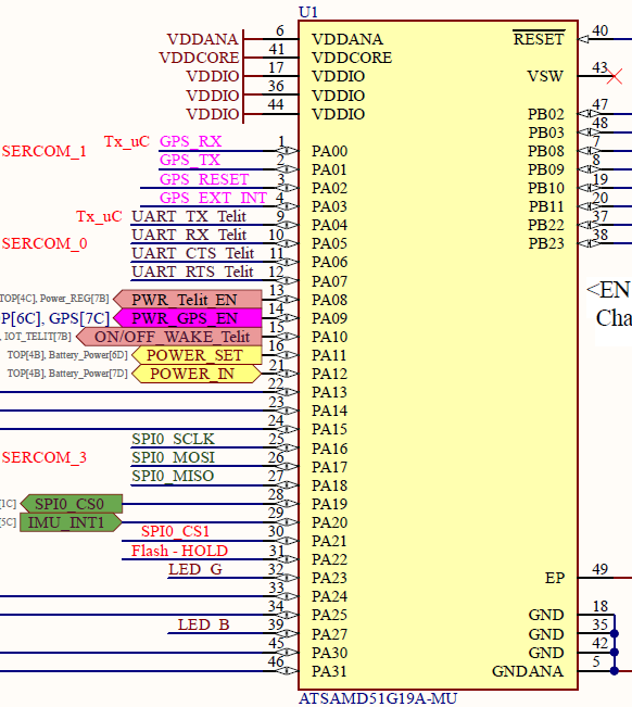
I am using SPI for 2 devices which they use:
MOSI -> PA17 -> { PORTA, 17, PIO_SERCOM_ALT, PIN_ATTR_PWM_F, No_ADC_Channel, TCC1_CH1, TC2_CH1, EXTERNAL_INT_1 }, // SERCOM 3.0 (MOSI)
MISO -> PA18 -> { PORTA, 18, PIO_SERCOM, PIN_ATTR_DIGITAL, No_ADC_Channel, NOT_ON_PWM, NOT_ON_TIMER, EXTERNAL_INT_2 }, // D7 // MISO SERCOM 1.3
SCK -> PA16 -> { PORTA, 16, PIO_SERCOM_ALT, PIN_ATTR_PWM_F, No_ADC_Channel, TCC1_CH0, TC2_CH0, EXTERNAL_INT_0 }, // SERCOM 3.1 (SCK)
CS0 -> PA19 -> { PORTA, 19, PIO_DIGITAL, PIN_ATTR_PWM_F, No_ADC_Channel, TCC1_CH3, TC3_CH1, EXTERNAL_INT_3 }, // D9
CS1 -> PA21 -> { PORTA, 21, PIO_DIGITAL, PIN_ATTR_PWM_G, No_ADC_Channel, TCC0_CH1, NOT_ON_TIMER, EXTERNAL_INT_5 }, // D11
I am also using 2 UART, in which the first one is using:
SERIAL2_TX -> PA01 -> { PORTA, 1, PIO_SERCOM, PIN_ATTR_NONE, No_ADC_Channel, NOT_ON_PWM, NOT_ON_TIMER, EXTERNAL_INT_1 }, // UART TX (SERCOM4 PAD 0)
SERIAL2_RX -> PA00 -> { PORTA, 0, PIO_SERCOM, PIN_ATTR_NONE, No_ADC_Channel, NOT_ON_PWM, NOT_ON_TIMER, EXTERNAL_INT_0 }, // UART RX (SERCOM4 PAD 1)
The other UART is using:
SERIAL1_TX -> PA04 -> { PORTA, 4, PIO_SERCOM_ALT, PIN_ATTR_DIGITAL, No_ADC_Channel, NOT_ON_PWM, NOT_ON_TIMER, EXTERNAL_INT_4 }, // UART TX (SERCOM0 PAD 0)
SERIAL1_RX -> PA05 -> { PORTA, 5, PIO_SERCOM_ALT, PIN_ATTR_DIGITAL, No_ADC_Channel, NOT_ON_PWM, NOT_ON_TIMER, EXTERNAL_INT_5 }, // UART RX (SERCOM0 PAD 1)
SERIAL1_CTS -> PA19 -> { PORTA, 19, PIO_DIGITAL, PIN_ATTR_PWM_F, No_ADC_Channel, TCC1_CH3, TC3_CH1, EXTERNAL_INT_3 }, // D9
SERIAL1_RTS -> PA07 -> { PORTA, 7, PIO_DIGITAL, PIN_ATTR_PWM_E, No_ADC_Channel, TC1_CH1, TC1_CH1, EXTERNAL_INT_7 }, // D2
Can someone help me in checking if the variant configuration I set is correct?
Also, in my code, I am using the following classes:
Serial2:
// Create a new UART instance for GNSS (SERCOM4)
static Uart GNSSUART(&sercom4, GNSS_RX_PIN, GNSS_TX_PIN, SERCOM_RX_PAD_1, UART_TX_PAD_0);
Serial1:
// Create a new UART instance using SERCOM3
static Uart TelitUART(&sercom3, UART_RX_PIN, UART_TX_PIN, SERCOM_RX_PAD_1, UART_TX_PAD_0);
SPI:
static SPIClass SPI_CUSTOM(&sercom1, MISO_PIN, SCK_PIN, MOSI_PIN, SPI_PAD_2_SCK_3, SERCOM_RX_PAD_0);
Lastly, I am using Arduino IDE, with ADAFRUIT ITSYBITSY board configuration, while my board is using ATSAMD51G19 microcontroller.
Thanks in advance.