Hello,
I've constructed two custom PCBs for two distinct projects. Both are designed for applications in a 12V car/truck environment. I'm experiencing similar issues with both, even though they have different designs to power a 12V motor.
Issue with PCB #1:
This Application uses a Mosfet and some Diodes and Resistors to engage the Motor.
I'm using D10 (MOSI) to detect a GND signal. I've enabled the internal pull-up resistor for this. When the device is exposed (no casing - and it's a solid aluminum casing), it functions correctly. However, when I place the casing on, anomalies occur.
When I activate the GND signal, there are times it detects and triggers repeatedly. At other times, it doesn't respond at all. I've added a buzzer to the PCB for feedback.

Code:
#include <Arduino.h>

const int triggerPin = A10;    // Pin connected to the trigger button
const int sensorPin1 = A5;     // Pin connected to one side of the sensor
const int sensorPin2 = A6;     // Pin connected to the other side of the sensor
const int motorPin = A7;       // Pin connected to the Mosfet for motor control
const int buzzerPin = A0;      // Pin connected to the positive side of the Buzzer
const int buzzerGndPin = A3;   // Pin connected to the negative side of the Buzzer

unsigned long motorStartTime = 0;
bool motorRunning = false;
bool triggerUsed = false;
unsigned long buzzerBeepTime = 0;

// Für die Entprellung
unsigned long lastTriggerTime = 0;
const int debounceTime = 50;  // Zeit in Millisekunden für die Entprellung

void setup() {
  pinMode(triggerPin, INPUT_PULLUP);
  pinMode(sensorPin1, INPUT_PULLUP);
  pinMode(sensorPin2, INPUT_PULLUP);
  pinMode(motorPin, OUTPUT);
  pinMode(buzzerPin, OUTPUT);
  pinMode(buzzerGndPin, OUTPUT);

  digitalWrite(buzzerGndPin, LOW);  // Set GND pin of Buzzer to LOW
  digitalWrite(motorPin, LOW);
}

void loop() {
  int triggerState = digitalRead(triggerPin);
  int sensorState1 = digitalRead(sensorPin1);
  int sensorState2 = digitalRead(sensorPin2);

  if (!triggerUsed && millis() - buzzerBeepTime >= 4000) {
    // Beep buzzer every 4 seconds if trigger has not been used yet
    beepBuzzer(500);
    buzzerBeepTime = millis();
  }

  if (triggerState == LOW && (millis() - lastTriggerTime) > debounceTime) {
    lastTriggerTime = millis();

    if (sensorState1 == HIGH && sensorState2 == HIGH && !motorRunning) {
      triggerUsed = true;
      motorRunning = true;
      motorStartTime = millis();
      digitalWrite(motorPin, HIGH); // Turn on the motor
      beepBuzzer(500); // Beep the buzzer when motor starts
    }
  }

  if (motorRunning && millis() - motorStartTime >= 5000) {
    digitalWrite(motorPin, LOW);  // Turn off the motor after 5 seconds
    motorRunning = false;
  }
}

void beepBuzzer(unsigned long duration) {
  digitalWrite(buzzerPin, HIGH);
  unsigned long beepStartTime = millis();
  while (millis() - beepStartTime < duration) {
    // Diese Schleife sorgt für die Dauer des Piepsens, aber ohne `delay`
  }
  digitalWrite(buzzerPin, LOW);
}
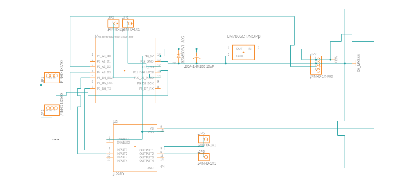
Issue with PCB #2:
This design employs an L293D to drive the motor in both directions.
For this PCB, I use a trigger signal to turn the motor clockwise. Additionally, I've incorporated a reed sensor to detect a magnet (positioned in the holder) which, when close, turns the motor counterclockwise.
However, I'm encountering a familiar issue.
Upon powering the unit, I receive sporadic trigger signals. For instance, when the motor is supposed to run continuously until a specific condition (like "Sensorbolzeneingefahren") is met, it unexpectedly halts and remains inactive until I re-trigger it. This happens even when the logical action would be to await the sensor trigger. Furthermore, the reed sensor is highly sensitive; merely approaching the cables with my fingers results in a trigger.
The reed sensor connects two pins on the Seeduino. Is there a method to detect this connection without applying current to them (akin to a pull-up)?
The trigger mechanism remains identical to that in PCB #1: a GND source connected to a pull-up pin.
Code:
const int reedInput = A7;
const int reedGround = D9;
const int buzzerPinPlus = A5;
const int buzzerPinMinus = A1;
const int triggerPin = A2;
const int input2L293D = A4;
const int input1L293D = A6;
const int sensorBolzenEingefahren = A3;
const int sensorBolzenAusgefahren = A10;

void setup() {
  pinMode(reedInput, INPUT);
  pinMode(reedGround, OUTPUT);
  digitalWrite(reedGround, HIGH);  // Setzt D9 auf HIGH

  pinMode(buzzerPinPlus, OUTPUT);
  pinMode(buzzerPinMinus, OUTPUT);
  pinMode(triggerPin, INPUT_PULLUP);
  pinMode(input2L293D, OUTPUT);
  pinMode(input1L293D, OUTPUT);
  pinMode(sensorBolzenEingefahren, INPUT_PULLUP);
  pinMode(sensorBolzenAusgefahren, INPUT_PULLUP);

  digitalWrite(buzzerPinMinus, LOW); // Ground for the buzzer
}

void loop() {
  // Bolzen ist eingefahren, warte auf Reed-Sensor, um auszufahren
  if (digitalRead(sensorBolzenEingefahren) == LOW) {
    if (digitalRead(reedInput) == HIGH) {
      buzzreed();
      while (digitalRead(sensorBolzenAusgefahren) == LOW) {
        extendBolzen();
      }
      stopMotor();
    }
  }
  // Bolzen ist nicht eingefahren (ganz oder teilweise ausgefahren), warte auf manuellen Trigger, um einzufahren
  else if (digitalRead(sensorBolzenEingefahren) == HIGH) {
    if (digitalRead(triggerPin) == LOW) {
      buzz();
      while (digitalRead(sensorBolzenEingefahren) == HIGH) {
        retractBolzen();
      }
      stopMotor();
    }
  }
}

void buzz() {
  digitalWrite(buzzerPinPlus, HIGH);
  delay(500); // Buzzer is on for 500 milliseconds
  digitalWrite(buzzerPinPlus, LOW);
}

void buzzreed() {
  digitalWrite(buzzerPinPlus, HIGH);
  delay(200); // Buzzer is on for 200 milliseconds
  digitalWrite(buzzerPinPlus, LOW);
}

void extendBolzen() {
  digitalWrite(input1L293D, HIGH);
  digitalWrite(input2L293D, LOW);
}

void retractBolzen() {
  digitalWrite(input1L293D, LOW);
  digitalWrite(input2L293D, HIGH);
}

void stopMotor() {
  digitalWrite(input1L293D, LOW);
  digitalWrite(input2L293D, LOW);
}
After extensive testing, I suspect the inconsistencies may stem from issues with the internal pull-up. Since all of them are used to detect trigger signals or sensor inputs. Are there alternative methods to utilize it? Or do i have a "stupid little mistake" going on?
