No thank you for taking your time to assist me, really appreciate it.
Running the code you provided in post#42
when connected to GND:
3.3v:
5v:
also the question marks were appearing due to my baud rate being higher then the code... really sorry about that.
Hi,
Okay,
How do you mean, did you have 9600 baud selected on the IDE monitor?
The results are good and in the right ball park.
Now try your code that I have edited.
When you make variables that show in the IDE as orange, it means they are assigned variables elsewhere in C++, it is best to avoid using them in my opinion.
This code compiles but I do not have the hardware to run it.
Connect your sensor up and see if you get stable readings.
int Rawval; // ADC value
int Pressoffset = 102; // ADC value @ 0 pressure
int adcMax = 921; // ADC value @ 5kPa (51 cmH2O)
int span;
int Newval;

void setup()
{
  Serial.begin(9600);
}

void loop()
{
  span = adcMax - Pressoffset; // 819 here
  Rawval = analogRead(A0);
  Serial.print(" Rawval = \t");
  Serial.print(Rawval);
  Newval -= Pressoffset;
  Serial.print("\t Pressure  = \t");
  float pressureVal = (float)Newval * 51.0 / (float)span;
  Serial.print(pressureVal, 1); // cmH2O
  Serial.println(" cmH2O");
  delay(2000);
}
Tom.. 


Thank you Tom,
these are the values i get
I get a stable output but when i apply pressure no change to the value occurs
Hi,
Does the Rawval change?
Is the schematic in post #3 yours?
If not.
Can you please post a copy of your circuit, in CAD or a picture of a hand drawn circuit in jpg, png?
Hand drawn and photographed is perfectly acceptable.
Please include ALL hardware, power supplies, component names and pin labels.
Thanks.. Tom..
`That schematic is indeed not mine
this circuit is though:
will this suffice?
zoomed in screenshot so you can see pin numbers:
Hi,
Export a jpg from your CAD, that will be of high enough resolution.
A schematic is better as it will show power and signal flow.
Thanks... Tom..
I can provide you with a pdf file because theres no option to export as jpg
Pin number 5 on pressure sensor is connected to A0 through a jumper cable, thats why ive written jump to pin 19
Hi,
Okay, also is that regulator a 5V regulator?
If so you connect it to 5V pin on the Nano, not Vin.
Currently you are powered from the PC USB so 5V is supplied.
On the PCB what is the second connection to the sensor output?
Tom..
Yes, im pretty sure either you or someone else made that suggestion very early on so i have put in place a boost buck converter which steps down voltage from 15v to 5v and powers through 5v pin. I just havent updated that change to my circuit diagram
the second connection is a BNC port which displays a flow graph which is dependant on pressure measurements
Hi,
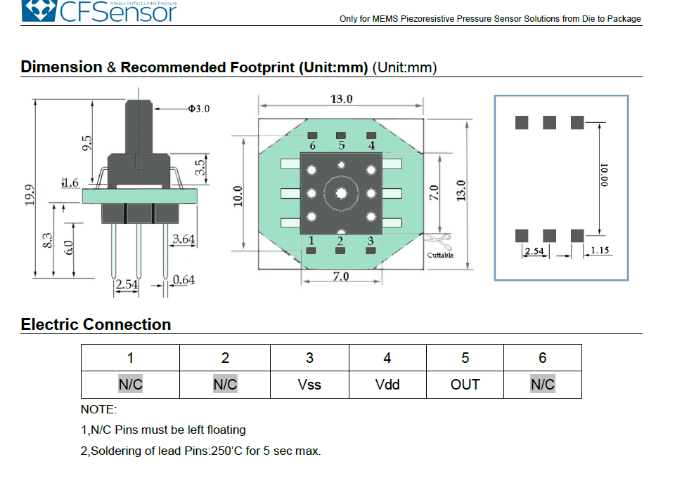
My spec sheet says
Note:
- The N/C pins MUST be left floating.
You have pin 2 connected to +5V.
This is for XGZP6847A
CZ_XGZP6847a010kpg_0001.pdf (509.2 KB)
Tom...
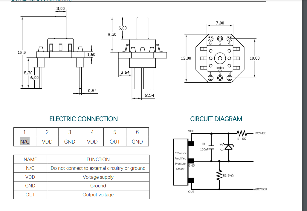
that is odd.
for the exact same model i have this:
XGZP6847A Pressure Sensor V2 4.pdf (902.7 KB)
should i try with pin 2 left floating?
Hi,
It might be worth a try.
Your datasheet says version 2.4, my copy does not have a version number.
Do you see the output change with a DMM connected to the sensor output?
Have you checked 5V and gnd connetions to the sensor?
What is the complete part number of the sensor?
Tom..
XGZP6847A100KPG.
will recheck connections right now
Maybe you could give a link to your copy of the data sheet.
Hi, @latedev
Another version of the datasheet, with pin 2 connected.
We await @idekman1813 to see if leaving it floating makes a difference.
Feels like we are so close to some variable readings as pressure is applied.
Tom..
Yep, just give me a minute