Hey Arduino Form users
I won't give too many specific details on what I'm building however one will easily pick it up given the context.
Anyway, I've got some thin film pressure sensors that I thought to use to measure subtle movements within the target area to then move servos or motors to the given range stated in the parameters of movement. However the sensors are sadly too sensitive and can be triggered with just holding the wires soldered to them. From what I have found, the arduino basically see's them as a "variable resistor" as there is only 2 legs (5v & Input). Because of this people have said that physical filters wouldn't be the best idea but I also have no idea how to set up a data filter on the software side as the "Average reading" filter that I found didn't work last time I tried it.
The plan is to have this sensor on a larger moving object (hand) and ignore all the small information, but as soon as the smaller object (muscle) moves against the sensor, I want the output to be related to servo movements without it "jerking" around as it is doing currently. I have managed to suppress the data somewhat by taking it from "0 , 1024 == 400 , 1024) in the code and that helped a tiny bit and can actuate the servos within the range set. but it still gives very sensitive data that spikes whenever it is moved.
So basically, can someone help me with code around this topic, or advice about it, if so that would be a massive help and much appreciated.
Can you please post link to spec/data of your film pressure sensor?
Can we please have a circuit diagram of how you have connected the sensor to the Arduino?
An image of a hand drawn schematic will be fine, include ALL power supplies, component names and pin labels.
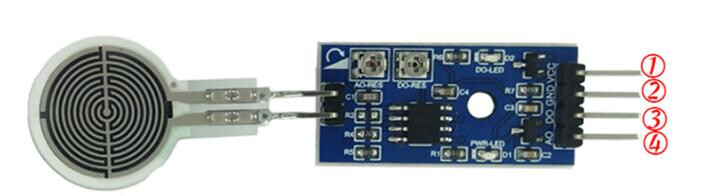
the specs are from an aliexpress listing as no one else sells them. This being said there is no data sheet for them. the information i was provided is that the smallest one i have ranged from 50g-2KG. i also have a 2.5KG-35KG. the company also sells a module that has more breakout pins for it but after connecting the sensor directly to my microcontroller, i found i did not need the module.
the way i have the sensor wired up is one leg goes to 3.3v and the other to input 1 on the board.
and the board I am using is a Seeduino XIAO.
Need to see how you have connected it?
Can we please have a circuit diagram?
An image of a hand drawn schematic will be fine, include ALL power supplies, component names and pin labels.
A link to the Aliexpress product will be helpful, as you might find someone here who has used that device before.
? I just don't see the need to show the project unless it can benefit in the aid of fixing it. If I need to show it then I can, i.e showing what the servos are doing in relation to the pressure sensor. I'm just about to figure out how to upload my code
/*
 Controlling a servo position using a potentiometer (variable resistor)
 by Michal Rinott <http://people.interaction-ivrea.it/m.rinott>

 modified on 8 Nov 2013
 by Scott Fitzgerald
 http://www.arduino.cc/en/Tutorial/Knob
*/

#include <Servo.h>

Servo myservo;  // create servo object to control a servo

int potpin = A1;  // analog pin used to connect the potentiometer
int val;    // variable to read the value from the analog pin
int FVal; //Filtered value


void setup()
{
  Serial.begin(9600);
  myservo.attach(A0);  // attaches the servo on pin 9 to the servo object
}


void loop()
{
  val = analogRead(potpin);            // reads the value of the potentiometer (value between 0 and 1023)
  val = map(val, 600, 1023, 180, 0);     // scale it for use with the servo (value between 180 and 0 to invert the motion)

  myservo.write(val);       // sets the servo position according to the scaled value
  Serial.println(val);
  delay(350);                           // waits for the servo to get there
}
Hi,
Glad you haven't tried the servo yet, it will have problems with 3V3 and the controller will not be able to supply the current it needs.
So remove it for the moment, just concentrate on getting proper sensor readings.
You need to solder a resistor between pin 1 and ground just like @jremington has been trying to tell you. Without one the sensor is not acting as a force sensor but as an antenna picking up electro magnetic signals from your body as you touch the wires.
As to the value, then measure the resistance of your sensor with a resistance setting on your Digital voltmeter and make this resistor roughly the same.
yes its just the sensor not the voltage converter they show.
As for resistance across the sensor, the highest I got was 6M ohm as it would just say it can't read it . and the lowest value was 3.9K ohm which was alot of force, far more than what would be needed.
also i forgot to mention, I am using 2g servo's currently but will be upgrading to 1.7g servos when I get a better model design to incorporate them.
No it wasn't working as a pressure sensor at all. You were just increasing the capacitive coupling between your body and the sensor, thus allowing more interference to be picked up. That is all.
Well I suspect that he gave up because you were ignoring him. Every reply to a thread is flagged up so that all people who have generated any response and have not turned off notifications.
On this forum the words "good luck with your project" actually means "I am disengaging with you because you are not cooperating so I am out of here" perhaps caused by you saying to the previous poster "don't see the need to show the project,". That meant you lost him before you posted your reply to him saying
Which is not very lucid is it? But as he went before you posted this he never saw it.
In fact having the reply at the end of the post is a bit useless and only came in with the latest revision of software. Most old hands here do not use that but just use the large "Reply button" at the end of the thread.


 it will have to be hand drawn sorry if it looks bad, dont have fritzing. but ill give it a shot, and also the code will come shortly